
Method for estimating clutch engagement parameters in a strategy for clutch management in a vehicle powertrain

Inactive Publication Date: 2007-12-20
EATON CORP
View PDF6 Cites 47 Cited by
  • Summary
  • Abstract
  • Description
  • Claims
  • Application Information

AI Technical Summary

Benefits of technology

[0007]An objective of the invention is to provide for an automatic control for clutch engagement management tha

Problems solved by technology

Although a correct functional relationship of clutch torque and clutch engagement angle can be precalibrated initially, clutch wear, which will inevitably take place due to numerous clutch engagements and disengagements, will result in a change in the functional relationship of clutch torque and engagement angle.
Shift quality then may deteriorate and clutch control system failures may occur because of excessive wear.
This deterioration of clutch performance due to wear also will affect vehicle launch from a standing start as the vehicle operator engages the clutch friction disks.
Currently, this clutch friction disk wear problem is dealt with by scheduling periodic time-consuming servicing of the vehicle, which results in an increase in overall operating costs and unproductive down-time for the vehicle.

Method used


Image

  • Method for estimating clutch engagement parameters in a strategy for clutch management in a vehicle powertrain
  • Method for estimating clutch engagement parameters in a strategy for clutch management in a vehicle powertrain
  • Method for estimating clutch engagement parameters in a strategy for clutch management in a vehicle powertrain

Examples


Embodiment Construction

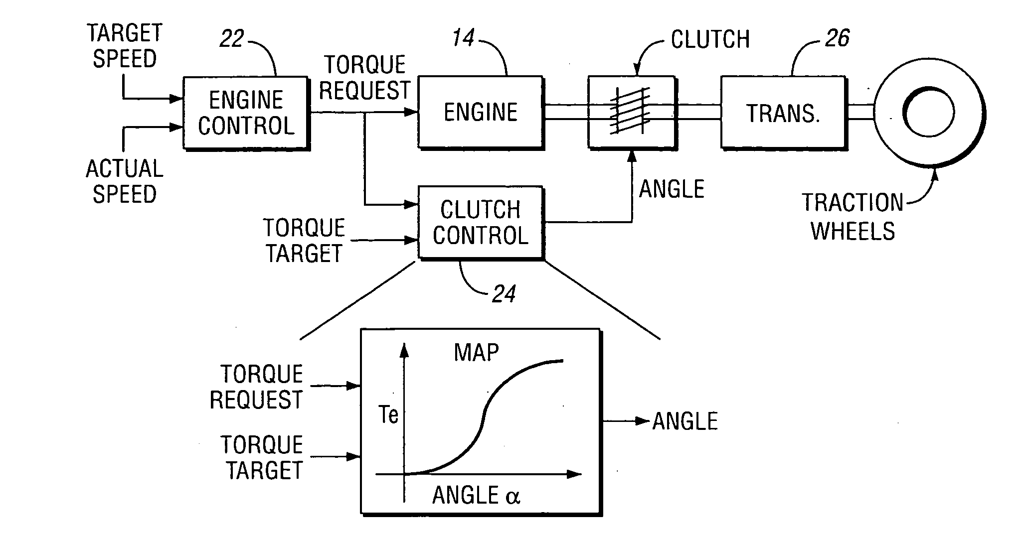
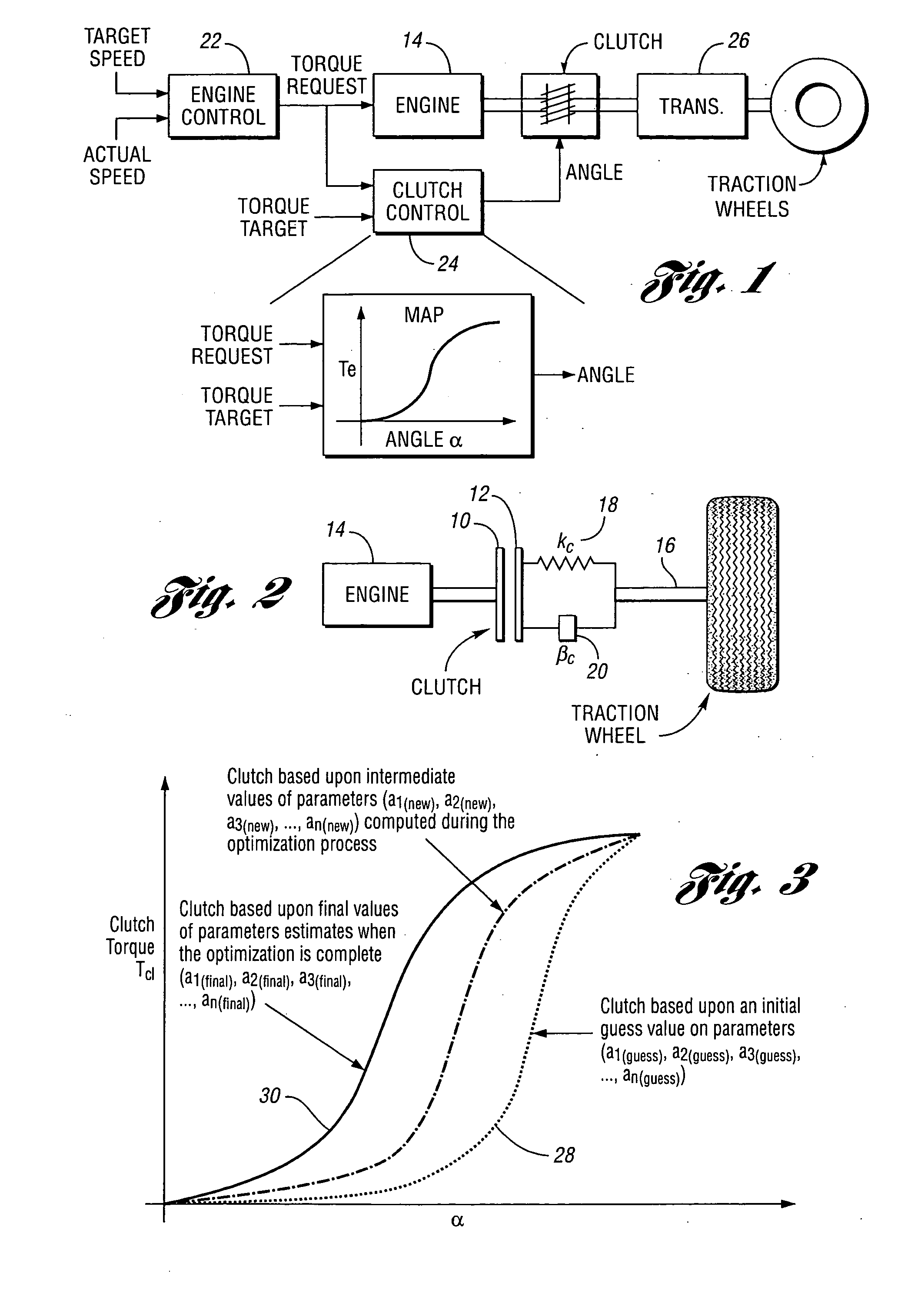
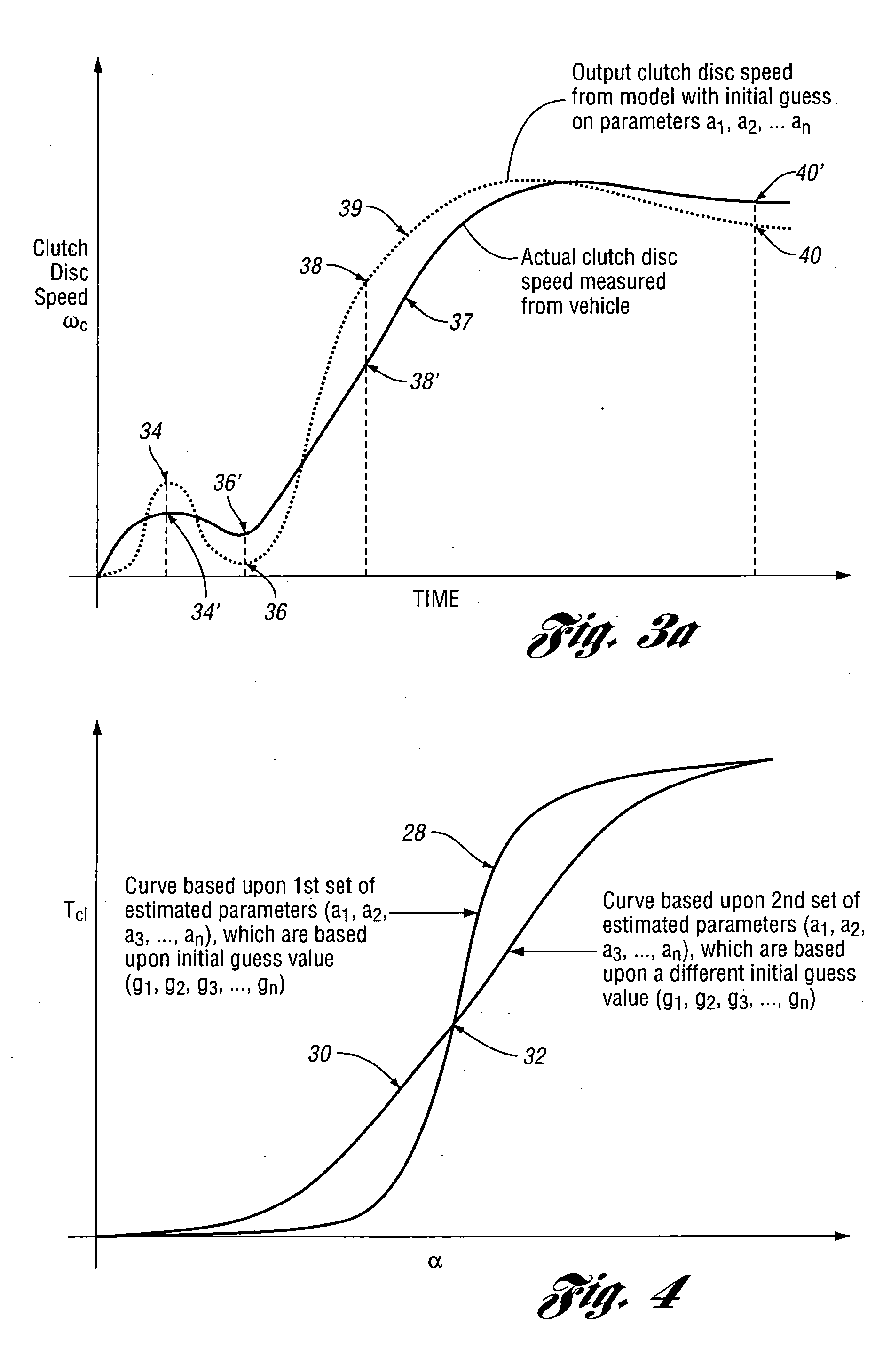
[0024]In the schematic diagram of FIG. 2, the clutch input friction disk is shown at 10 and the clutch output friction disk is shown at 12. Disk 10 is drivably connected to engine 14. The clutch output disk is drivably connected to a transmission mainshaft or a driveline driveshaft 16. Driveline elasticity is schematically represented by a spring constant 18 (Kc), and a vibration damper constant is schematically represented by at 20 (βc). During upshifts and downshifts of the transmission, or during vehicle launch, torque delivery from the engine is interrupted as the clutch disks 10 and 12 are opened. A dynamic model of the entire system can be found by applying a torque equilibrium condition at various nodes in the structure. The dynamic equations for the driveline shown in FIG. 2, when the clutch is slipping in an engagement mode, are indicated as follows:

ω.e=-βeJeωc-1JeTcl+1JeTe(1)ω.c=-βcJcωc-1JcTl+1JcTcl(2)Tcl=F(α,α0,α1,α2,…,αn)(3)

[0025]where:

[0026]ωe=Engine speed, measured on ...


PUM


Abstract

A method is disclosed for estimating clutch engagement characteristics of a friction clutch system in a vehicle powertrain. A dynamic model of the system is used under conditions that cause clutch slipping. Algebraic equations defining a functional relationship between clutch torque and an engagement angle have characteristic parameters that are estimated using a non-linear least squares technique. A non-linear least squares technique iteratively minimizes the difference between a measured output clutch disk speed and an output clutch disk speed from the system dynamic model for the same inputs until a small insignificant error is reached. Parameter estimates are used to compile an estimated clutch engagement characteristic.

Description

BACKGROUND OF THE INVENTION[0001]1. Field of the Invention[0002]The invention relates to a method for modifying friction clutch engagement characteristics to compensate for clutch wear.[0003]2. Background of the Invention[0004]In a typical powertrain system for road vehicles, such as light-duty trucks and heavy-duty trucks, torque is delivered from the vehicle engine to the torque input side of a multiple-ratio transmission through a friction clutch that is under the control of the vehicle operator. Torque is transmitted from a torque output portion of the transmission through a transmission mainshaft, a driveshaft and a differential-and-axle assembly to vehicle traction wheels. A vehicle operator may change the overall speed ratio of the powertrain by selectively engaging and disengaging clutch elements or brake elements in the transmission as the transmission drive ratio is upshifted and downshifted. To effect an upshift or a downshift, the operator typically will open the frictio...

Claims


Application Information

Patent Timeline
IPC IPC(8): G06F17/00
CPCF16D48/06F16D2500/3165Y10T477/70F16D2500/70605F16D2500/7082F16D2500/70264
Inventor JOSHI, SAMEER A.SURIANARAYANAN, ANANTHAKRISHNANLIU, CHIA-HSIANG
Owner EATON CORP
Learn More