Sensor and receiving device in sensor system
a sensor and receiving device technology, applied in the field of sensor systems, can solve problems such as difficulty in achieving miniaturization
- Summary
- Abstract
- Description
- Claims
- Application Information
AI Technical Summary
Benefits of technology
Problems solved by technology
Method used
Image
Examples
first example
4.1) First Example
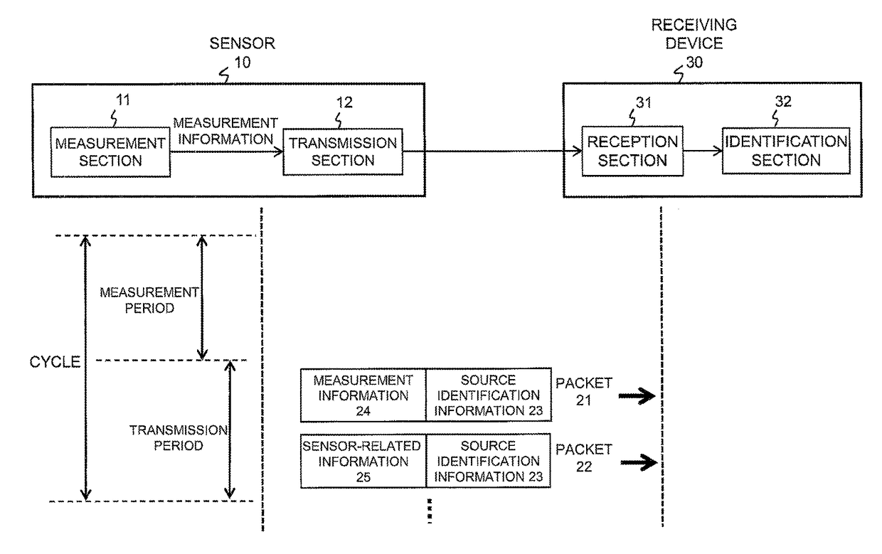
[0061]According to a first example of the present invention, a local ID as source identification information, sampling data as measurement information, and product type data as sensor-related information are transmitted by using a single packet with a predetermined format.
[0062]Referring to FIG. 8, a packet 510 includes a local ID 511 and a data area 512, and the data area 512 includes sampling data 513 and product type data 514. In the present example, it is assumed that the packet length of a whole packet is 30 bits, of which 7 bits are for the local ID 511, 12 bits are for the sampling data 513, and 11 bits are for the product type data 514. The local ID 511 is identification information for identifying the source of a packet and is identification information identifiable particularly in a local network. The sampling data 513 is a measurement result sampled at sampling intervals.
[0063]The product type data 514 is information related to a sensor and is informatio...
second example
4.2) Second Example
[0067]According to a second example of the present invention, a local ID as source identification information, sampling data as measurement information, and an extended ID as sensor-related information are transmitted by using two packets in which packet's data types are changed.
[0068]Referring to FIG. 9, a packet 520 includes a local ID 521, a type flag 522, and a data area 523. The data area 523 can include either an extended ID 524 or sampling data 525. The packet 520 according to the present example is a total of 20 bits, of which 7 bits are for the local ID 521, 1 bit is for the type flag 522, and 12 bits are for the data area 523. The type flag 522 takes on “0” or “1,” thereby showing which one of the extended ID 524 and the sampling data 525 the subsequent data area 523 includes.
[0069]The extended ID 524 is an ID for identifying a sensor, extending the local ID to enable more sensors to be identified.
[0070]Referring to the sensor circuit 210 shown in FIG. 3...
third example
4.3) Third Example
[0073]According to a third example of the present invention, a local ID as source identification information, sampling data as measurement information, and a unique ID as sensor-related information are transmitted by using two packets in which packet's data types are changed.
[0074]Referring to FIG. 10, a packet 530 includes a local ID 531, a type flag 532, and a data area 533, and the data area 533 includes either a unique ID 534 or sampling data 535. Compared with the second example shown in FIG. 9, a difference is the unique ID in place of the extend ID, and the other components and the bit length are similar.
[0075]The unique ID is an ID for identifying a sensor or a sensor-target equipment and has a longer length than a local ID, preferably, has as large a number of bits as can accommodate one ID in terms of practical use. That is, it is assumed here that the unique ID is 12 bits, but it suffices if the unique ID is larger than the local ID of 7 bits. For exampl...
PUM
 Abstract
Description
Claims
Application Information
 - R&D
- Intellectual Property
- Life Sciences
- Materials
- Tech Scout
- Unparalleled Data Quality
- Higher Quality Content
- 60% Fewer Hallucinations
Browse by: Latest US Patents, China's latest patents, Technical Efficacy Thesaurus, Application Domain, Technology Topic, Popular Technical Reports.
© 2025 PatSnap. All rights reserved.Legal|Privacy policy|Modern Slavery Act Transparency Statement|Sitemap|About US| Contact US: help@patsnap.com


