Firearm handgrip assembly with laser gunsight system

a laser gun sight and handgrip technology, applied in the field of handgrip assemblies, can solve the problems of difficult aiming and shooting accurately, repeated laser sighting process, and inability to guarantee the accuracy of laser beams reflecting the point of impact of firearms, so as to improve the appreciation of contributions to the art

Active Publication Date: 2016-01-26
HOGUE
View PDF50 Cites 30 Cited by
  • Summary
  • Abstract
  • Description
  • Claims
  • Application Information

AI Technical Summary

Benefits of technology

The technical effect of this patent is to provide an outline of the main features of the invention for easy understanding by those skilled in the field. This helps them to follow the details of the invention when it is described in detail later on.

Problems solved by technology

The technical problem addressed in this patent text relates to improving firearm handgrip assemblies that incorporate a laser gunsight system with batteries that can be easily changed without removing the laser from the firearm. Additionally, it seeks to improve the design of the handgrip assembly to better fit different users' preferences and comfort levels, including those with larger hands.

Method used


Image

  • Firearm handgrip assembly with laser gunsight system
  • Firearm handgrip assembly with laser gunsight system
  • Firearm handgrip assembly with laser gunsight system

Examples


Embodiment Construction

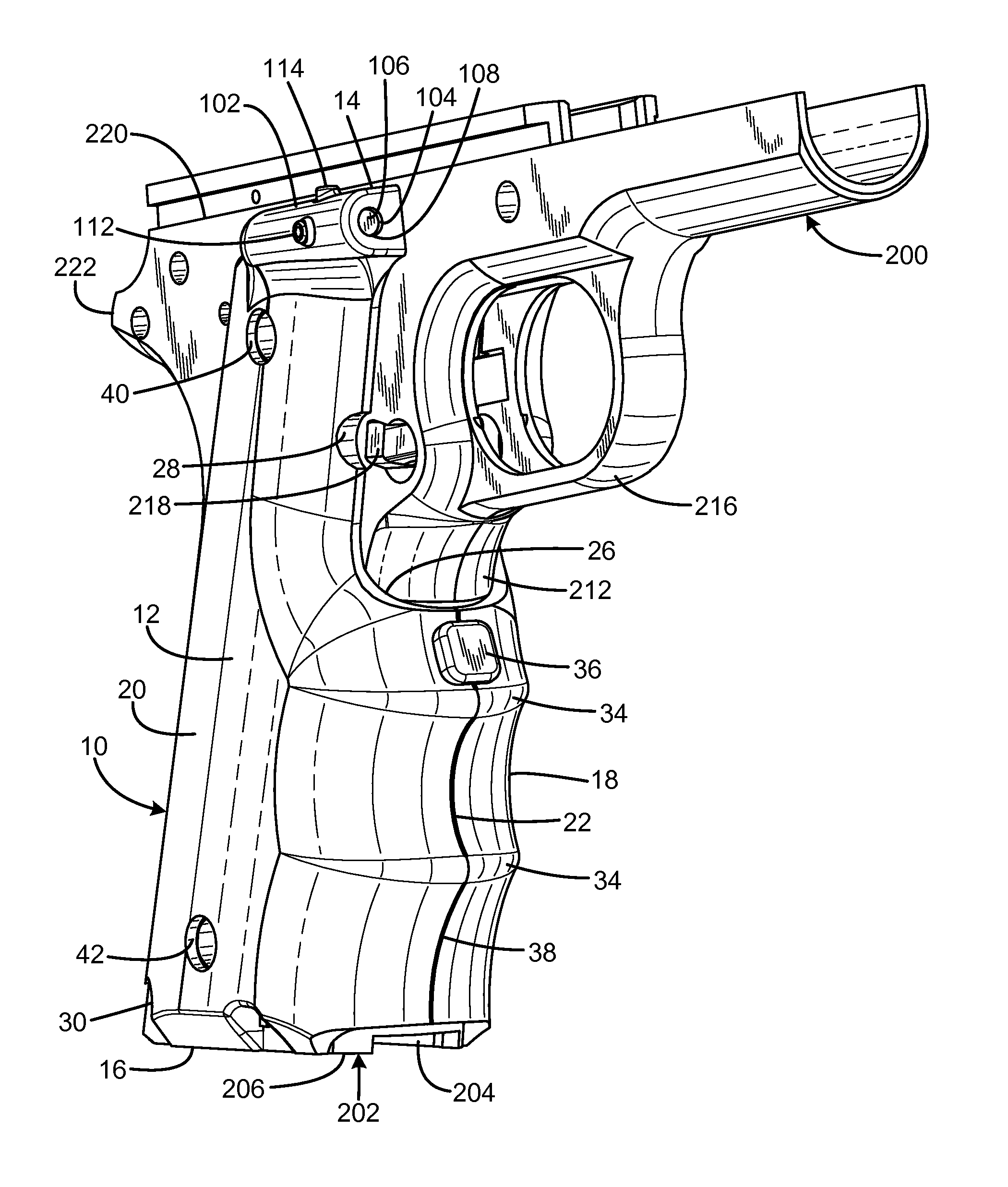
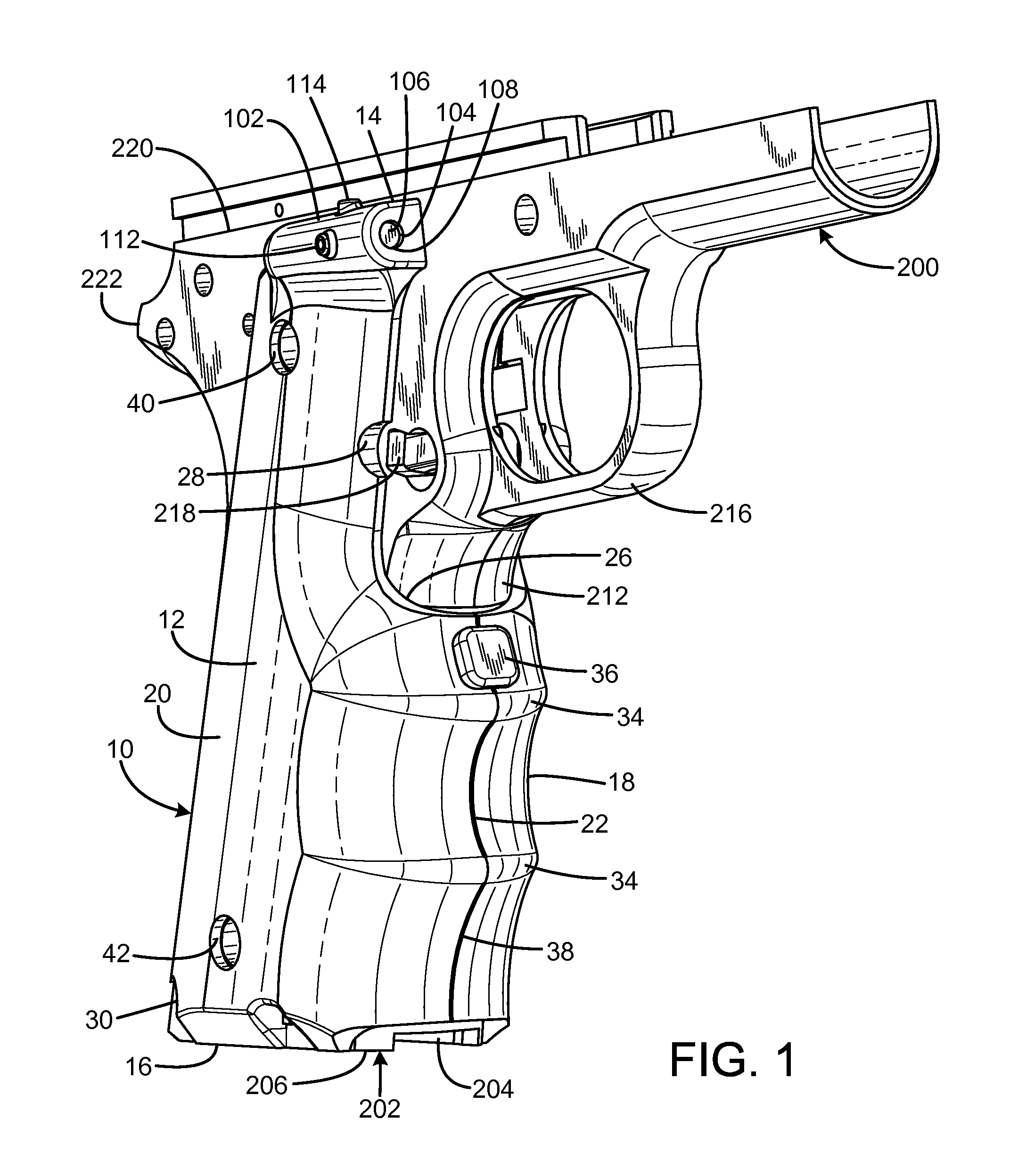
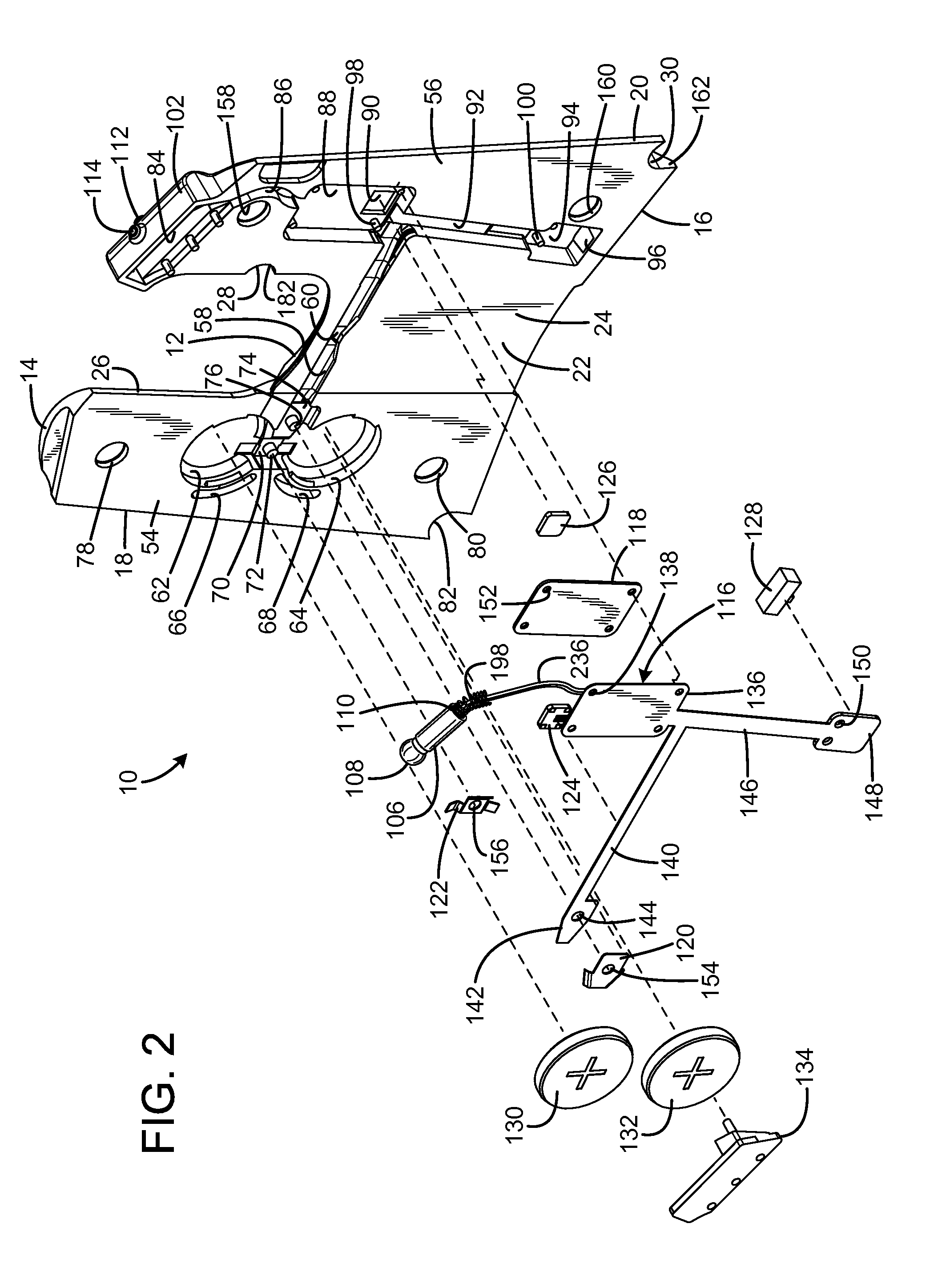
[0026]An embodiment of the firearm handgrip assembly with laser gunsight system of the present invention is shown and generally designated by the reference numeral 10.

[0027]FIGS. 1-4 illustrate the improved firearm handgrip assembly with laser gunsight system 10 of the present invention for use with a pistol having removable grips. This type of pistol typically has a molded plastic grip with a curved exterior to be comfortably received in a user's hand. The pistol includes a removable back strap insert (not shown). Only the frame 200 of the pistol is illustrated for clarity. More particularly, the one-piece integrally molded plastic frame shown is for an M1911 pistol.

[0028]The frame 200 has a downwardly-extending handgrip 202 that angles slightly rearward and is a tubular body defining an elongated well 204 capable of closely receiving a removable magazine (not shown). The handgrip has a lower free end 206. The grip has flat or gently curved right and left side portions 208, 210, a ...


PUM


Abstract

A firearm handgrip assembly with laser gunsight system has a first grip body having a first attachment facility operable to connect the grip to the frame at a first frame position, a second grip body having a second attachment facility operable to connect the grip to the frame at a first frame position, a connection portion connected to the first grip body and to the second grip body, the first grip body including a beam projection element, the second grip body including a power storage facility, and the second attachment facility being operable to enable detachment and reattachment of the second grip body while the first grip body remains undisturbed, such that batteries may be replaced without disturbing the alignment of the beam projection element. The connection portion may include a conductor and be formed of a flexible material, such as an elastomer.

Description


Claims


Application Information

Patent Timeline
Owner HOGUE
Why Eureka
Try Eureka