Adjustable rifle telescope system with multiple fixed angle mount setpoints

a telescope system and adjustable technology, applied in the field of adjustable rifle telescope systems, can solve the problems of limited adjustment range of internal optical adjustments, general unpractical approach, and bulkier designs with a greater adjustment range. , to achieve the effect of better appreciation of the contribution of the ar

Active Publication Date: 2009-12-17
BARRETT FIREARMS MFG INC
View PDF13 Cites 27 Cited by
  • Summary
  • Abstract
  • Description
  • Claims
  • Application Information

AI Technical Summary

Benefits of technology

[0010]There has thus been outlined, rather broadly, the more important features of the invention in order that the detailed description thereof that follows may be better understood and in order that the present contribution to the art may be better appreciated.

Problems solved by technology

While it is possible in some instances to mount a scope with its optical axis parallel to the barrel bore axis and employ the optical adjustment to compensate for bullet drop, this approach is generally not considered practical.
Internal optical adjustments have limited ranges of adjustment, and designs that have greater adjustment range are bulkier than is desirable.
While an angled mount is effective for a single selected cartridge having known flight characteristics and for a scope having known adjustment capabilities, a single angled mount is not suitable for a varied range of cartridges or versatile for a range of different scope types.
However, these are less robust systems than the present invention and suffer from backlash that can make repeatable settings unreliable.

Method used


Image

  • Adjustable rifle telescope system with multiple fixed angle mount setpoints
  • Adjustable rifle telescope system with multiple fixed angle mount setpoints
  • Adjustable rifle telescope system with multiple fixed angle mount setpoints

Examples


Embodiment Construction

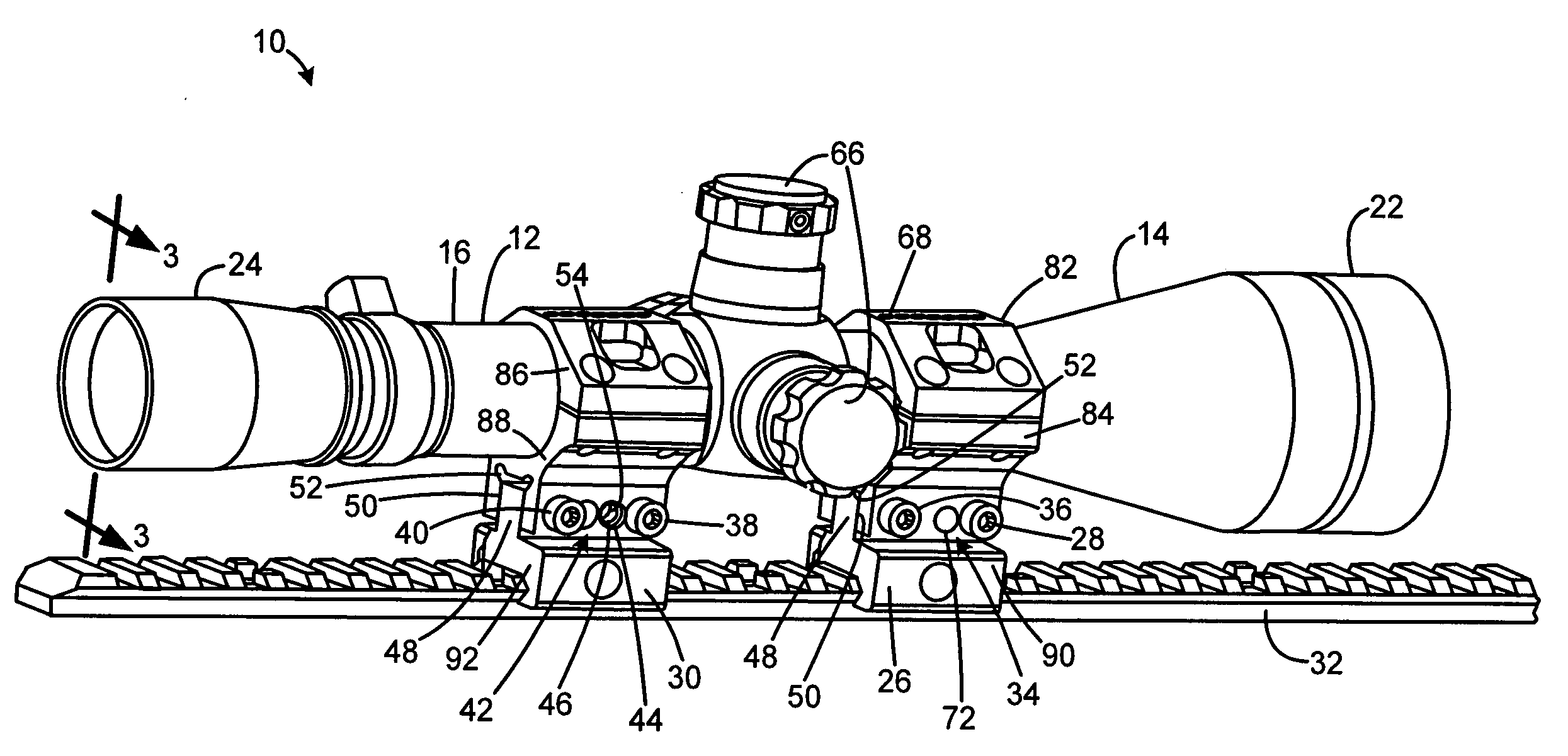
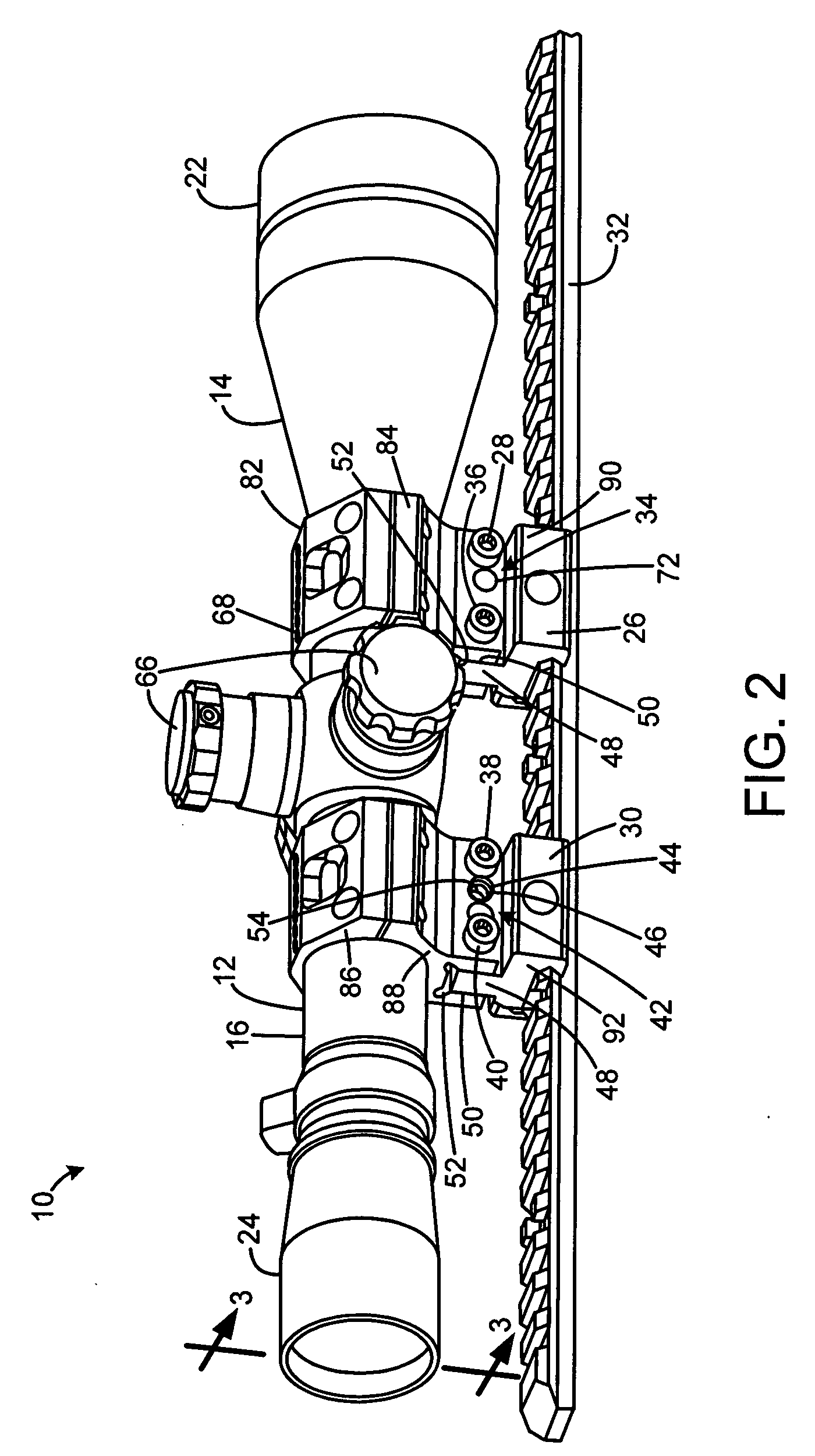
[0019]A preferred embodiment of the adjustable rifle telescope system with multiple fixed angle mount setpoints of the present invention is shown and generally designated by the reference numeral 10.

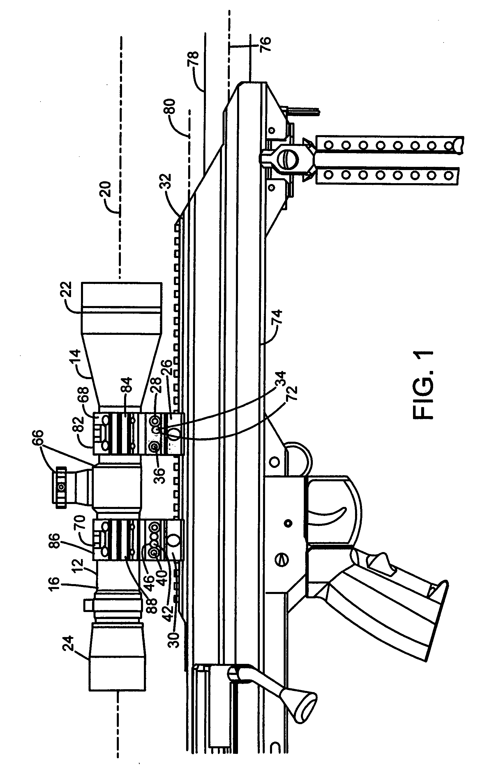
[0020]FIG. 1 illustrates an improved adjustable rifle telescope system with multiple fixed angle mount setpoints 10 of the present invention. More particularly, the adjustable rifle telescope system with multiple fixed angle mount setpoints 10, also known as a riflescope or telescopic rifle sight, is depicted attached to a firearm 74 by a rail 32. The rifle 74 has a barrel 78, which is a hollow metal tube. The barrel 78's interior diameter defines the barrel 78's bore. The center of the barrel 70's bore defines the barrel bore axis 76. The rail axis 80, defined by the centerline of rail 32, is depressed by 20-30 MOA (Minutes of Angle) in typical applications with respect to the barrel bore axis 76. The scope system 110's optical axis 20 is defined by the centers of the front scope rings ...


PUM


Abstract

A rifle telescope has optics having an optical axis, a scope support portion that supports the optics, and a base portion that mounts to a firearm having a barrel axis. The scope support portion has at least two different settings, each setting providing a different angle between the optical axis and the barrel axis. The invention may also include each setting being a discrete fixed setting. The present invention also includes a method for adjusting the angle mount of an adjustable rifle telescope with multiple fixed angle mount setpoints.

Description

FIELD OF THE INVENTION[0001]The present invention relates to an adjustable rifle telescope system with multiple fixed angle mount setpoints for use in connection with firearms. The adjustable rifle telescope system with multiple fixed angle mount setpoints has particular utility in connection with enabling accurate long-distance shooting where significant elevation compensation is required.BACKGROUND OF THE INVENTION[0002]Adjustable rifle telescopes with multiple fixed angle mount setpoints are desirable for enabling accurate long-distance shooting where significant elevation compensation is required. Optical scopes are mounted on rifles to provide a clear magnified image of a target and to provide an adjustable aiming point to indicate the point of impact of a projectile on a target. Scopes typically have an internal optical adjustment to shift the image or apparent location of the crosshairs to compensate for the amount that the bullet drops below the axis of the barrel as it flie...

Claims


Application Information

Patent Timeline
Patent Type & Authority Applications(United States)
IPC IPC(8): F41G1/387
CPCF41G1/38F41G11/003F41G1/387
Inventor BARRET, CHRISTOPHER GENE
Owner BARRETT FIREARMS MFG INC
Why Eureka
Try Eureka