Forearm-gripping stabilizing attachment for a handgun

a technology for stabilizing attachments and handguns, applied in the direction of arms wearables, weapons, butts, etc., can solve the problem of becoming more difficult in one-handed operation, and achieve the effect of improving the appreciation of the contribution to the ar

Active Publication Date: 2014-05-29
NST GLOBAL
View PDF10 Cites 26 Cited by
  • Summary
  • Abstract
  • Description
  • Claims
  • Application Information

AI Technical Summary

Benefits of technology

[0008]There has thus been outlined, rather broadly, the more important features of the invention in order that the detailed description thereof that follows may be better understood and in order that the present contribution to the art may be better appreciated.
[0009]Numerous objects, features and advantages of the present invention will be readily apparent to those of ordinary skill in the art upon a reading of the following detailed description of present, but nonetheless illustrative, embodiments of the present invention when taken in conjunction with the accompanying drawings. The invention is capable of other embodiments and of being practiced and carried out in various ways. Also, it is to be understood that the phraseology and terminology employed herein are for the purpose of descriptions and should not be regarded as limiting.

Problems solved by technology

The accuracy and proficiency of firing a handgun greatly depends upon the user's ability to hold the handgun in a steady position while firing, which becomes more difficult in one handed operation.
Holding a handgun in a steady position can be a difficult challenge to person having a physical disability that prevents that person from being able to firmly grip the handgun or steady the handgun for any appreciable length of time to permit accurate firing.
This becomes an even further challenge when the weight of the handgun is concentrated forwardly of the pistol grip and causes the handgun to want to dip forwardly and, thus, require the user to compensate for this imbalance by continuously applying an upwardly force upon the grip to bring the handgun into a correct firing position.

Method used


Image

  • Forearm-gripping stabilizing attachment for a handgun
  • Forearm-gripping stabilizing attachment for a handgun
  • Forearm-gripping stabilizing attachment for a handgun

Examples


Embodiment Construction

[0022]As a preliminary matter, it should be noted that in this document directional terms, such as “above”, “below”, “upper”, “lower”, etc., are used for convenience in referring to the accompanying drawings.

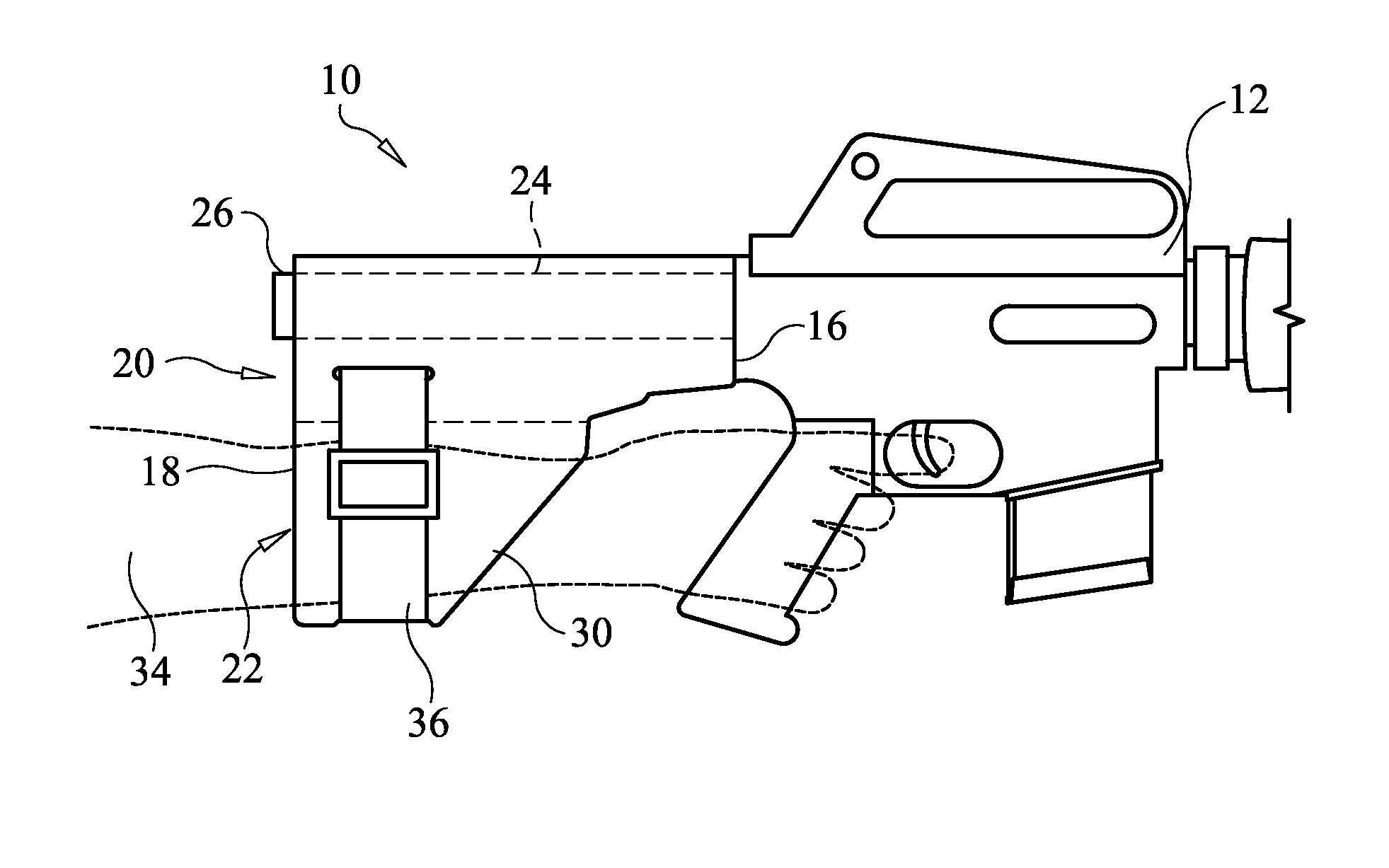
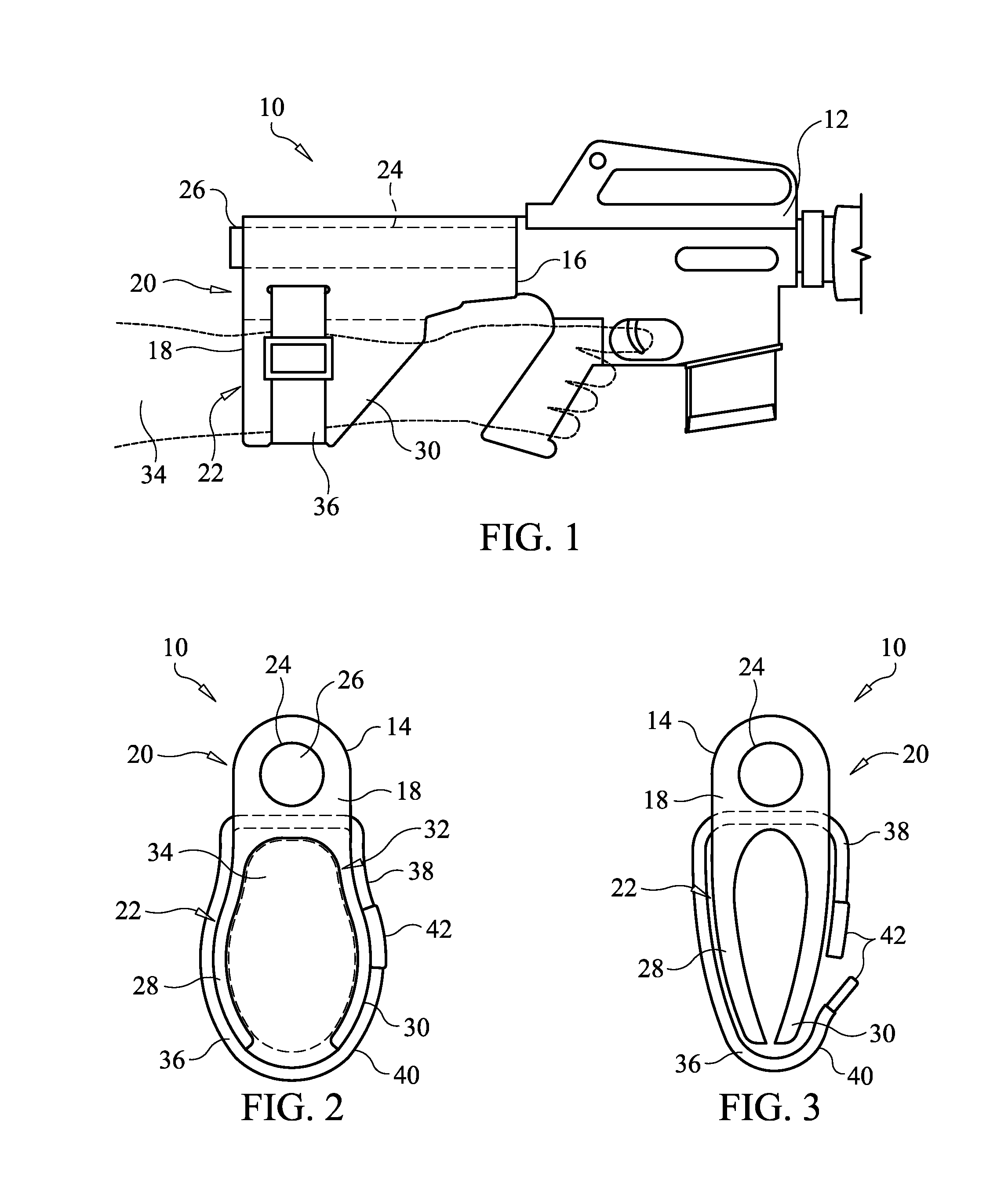
[0023]In FIGS. 1 through 3, there is representatively illustrated a specially designed stabilizing attachment 10, for mounting to a handgun 12, that permits a user to handle and support a handgun without straining the user's arm, hand, or wrist. Stabilizing attachment 10 is particularly advantageous for a person having a physical disability that would prevent the person from handling and supporting the handgun for an appreciable amount of time. Stabilizing attachment 10 is also particularly useful with handguns having a large portion of its weight located forwardly of the pistol grip that causes a user to strain to properly hold the handgun in a correct firing position.

[0024]Stabilizing attachment 10 comprises body 14, which in an embodiment, is made substantially of a semi-rigi...


PUM


Abstract

A forearm-gripping stabilizing attachment for a handgun that has a support structure extending rearwardly from the rear end of the handgun is provided. The forearm-gripping stabilizing attachment includes a body having a passage longitudinally extending therein. The support structure of the handgun is telescopically receivable by the passage to secure the stabilizing attachment to the handgun. The body is further configured to receive and grip a user's forearm such that the support structure extends along the user's forearm. The stabilizing attachment is particularly useful in aiding a physically disabled user with handling the handgun because the handgun essentially becomes an extension of the user's forearm such that the user may actually release his or her grip from the handgun to relax the user's hand between firing while still maintaining proper control of the handgun at all times.

Description

CROSS-REFERENCE TO RELATED APPLICATIONS[0001]This application claims the benefit of provisional patent application Ser. No. 61 / 730,077, filed Nov. 27, 2012, the entirety of which is incorporated herein by reference.FIELD OF THE INVENTION[0002]The present invention relates generally to a stabilizing attachment for a handgun and, more particularly, to a forearm-gripping stabilizing attachment for a handgun that secures to a rearward end of the handgun frame and engages a user's forearm.BACKGROUND OF THE INVENTION[0003]The accuracy and proficiency of firing a handgun greatly depends upon the user's ability to hold the handgun in a steady position while firing, which becomes more difficult in one handed operation. Holding a handgun in a steady position can be a difficult challenge to person having a physical disability that prevents that person from being able to firmly grip the handgun or steady the handgun for any appreciable length of time to permit accurate firing. This becomes an e...

Claims


Application Information

Patent Timeline
Patent Type & Authority Applications(United States)
IPC IPC(8): F41C23/10
CPCF41C23/12F41C23/10F41C33/001
Inventor BOSCO, ALESSANDRO ROBERTO
Owner NST GLOBAL
Why Eureka
Try Eureka