Assembly for coping and mounting trim molding

a technology for coping and trim molding, applied in the field of finishing carpentry, can solve the problems of square joint but often not working, and achieve the effect of better appreciation of the contribution to the ar

Active Publication Date: 2013-02-28
ARMACOST GREGORY SCOTT
View PDF6 Cites 30 Cited by
  • Summary
  • Abstract
  • Description
  • Claims
  • Application Information

AI Technical Summary

Benefits of technology

[0018]The coping device also can further include a plurality of interchangeable cutter blades, each cutter blade configured to a specific profile desired to be cut into the finish trim molding. The coping device also includes a pivot upon which the blade assembly having the cutter blade is moved by the lever. The coping device is a manual, non-electric device.
[0019]There has thus been outlined, rather broadly, the more important features of the technology in order that the detailed description thereof that follows may be better understood, and in order that the present contribution to the art may be better appreciated. There are additional features of the technology that will be described hereinafter and which will form the subject matter of the claims appended hereto. In this respect, before explaining at least one embodiment of the technology in detail, it is to be understood that the invention is not limited in its application to the details of construction and to the arrangements of the components set forth in the following description or illustrated in the drawings. The technology described herein is capable of other embodiments and of being practiced and carried out in various ways. Also, it is to be understood that the phraseology and terminology employed herein are for the purpose of description and should not be regarded as limiting.

Problems solved by technology

Traditional miter-cutting at forty-five degree angles may provide a square joint but often does not work since most wall corners are not square, and, thus, do not have a true ninety-degree angle.

Method used


Image

  • Assembly for coping and mounting trim molding
  • Assembly for coping and mounting trim molding
  • Assembly for coping and mounting trim molding

Examples


Embodiment Construction

[0031]Before describing the disclosed embodiments of this technology in detail, it is to be understood that the technology is not limited in its application to the details of the particular arrangement shown here since the technology described is capable of other embodiments. Also, the terminology used herein is for the purpose of description and not of limitation.

[0032]In various exemplary embodiments, the technology described herein provides for an assembly and associated methods for coping and mounting finish trim molding.

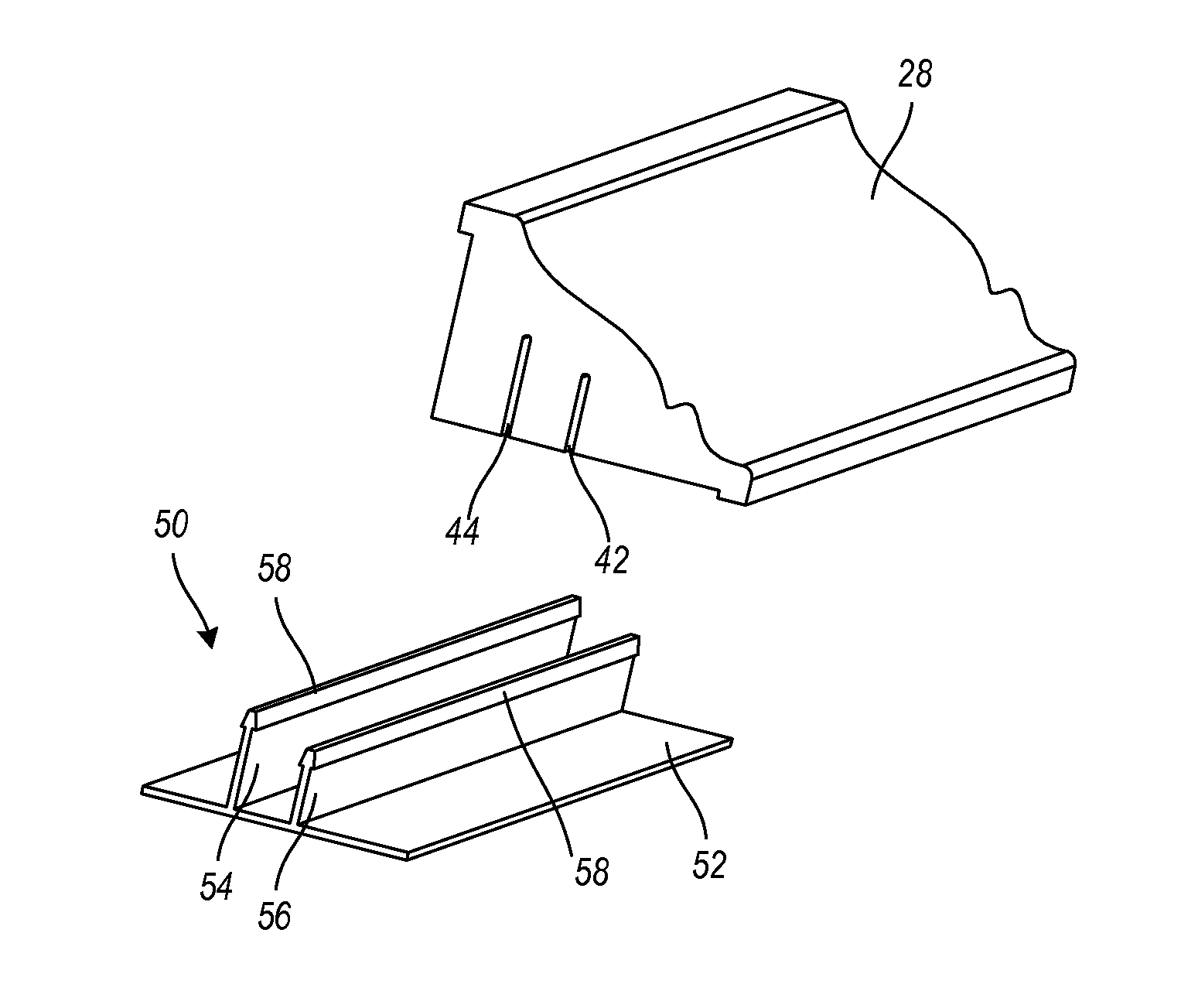
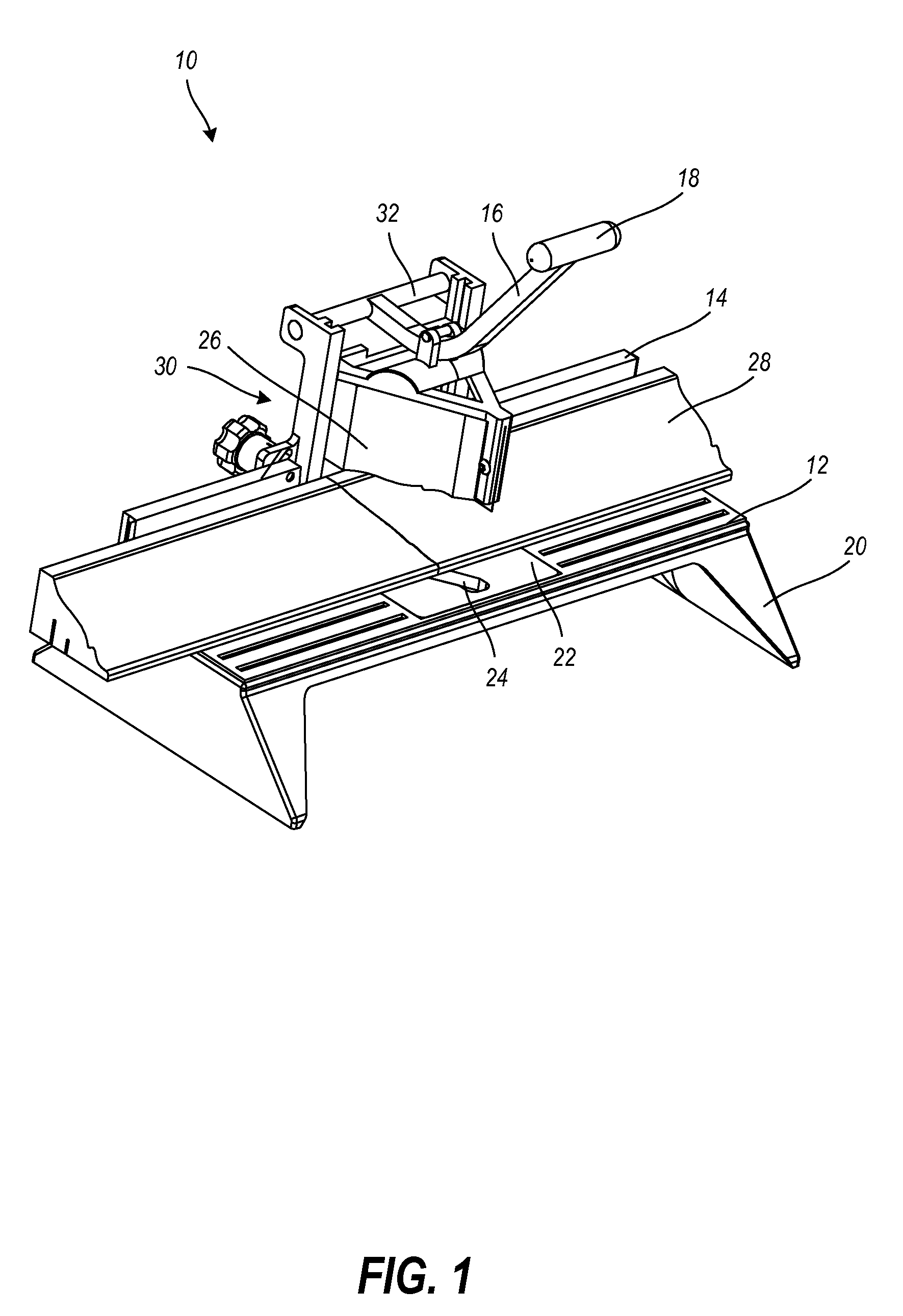
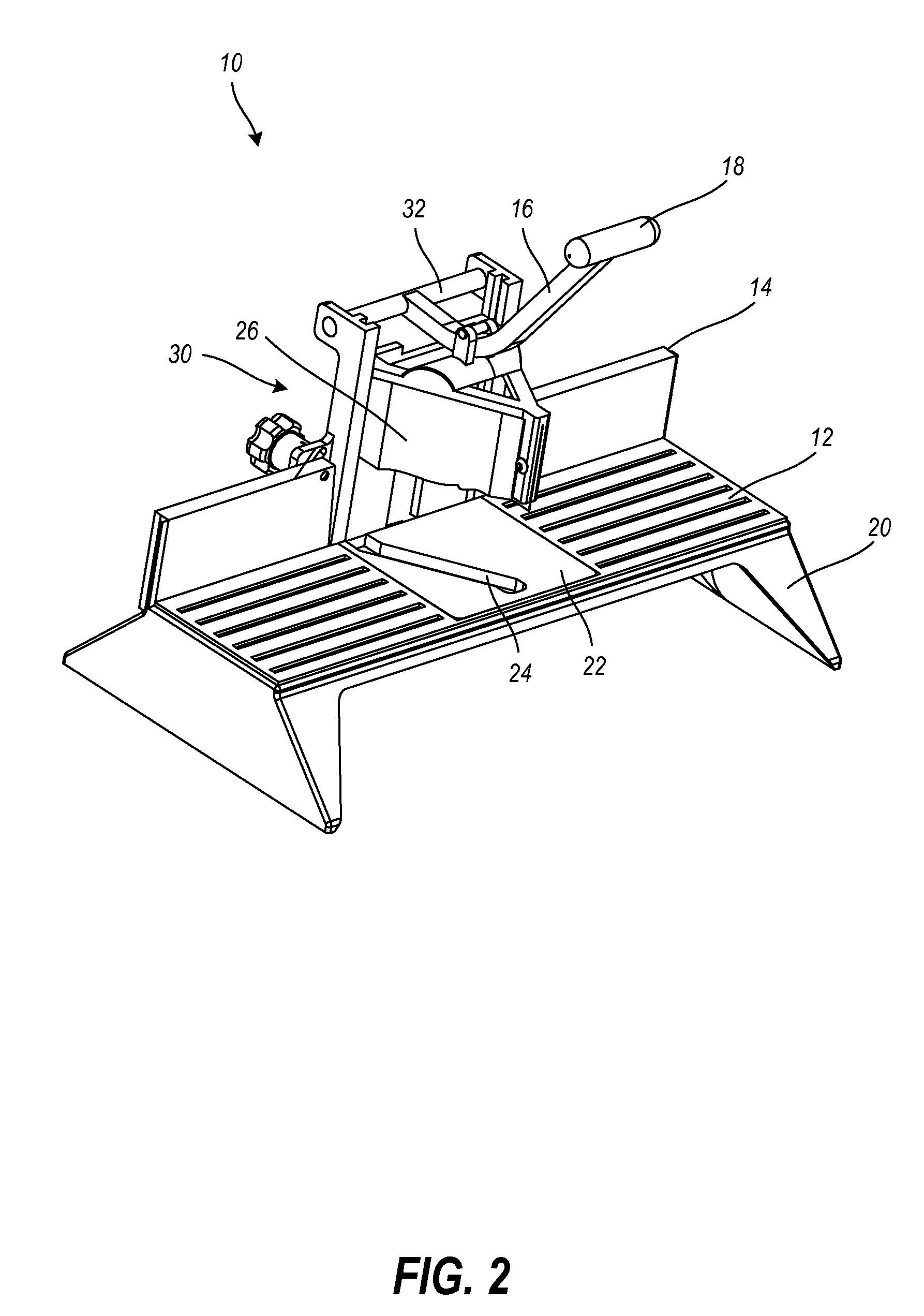
[0033]Referring now to the Figures, a coping device 10 for coping finish trim molding is shown. The coping device 10 depicted is a manual, non-electric device. The coping device 10 can be used, for example, to cut a piece of finish trim molding 28, such as a piece of foam trim. When finish trim meets in a corner, the corner is not always originally found at a perfect 90 degree angle. Under such circumstances, one can cope the trim so that no matter what angle th...


PUM

PropertyMeasurementUnit
90 degree angleaaaaaaaaaa
sizeaaaaaaaaaa
angleaaaaaaaaaa

Abstract

An assembly for coping and mounting trim molding is provided. A trim holding device for mounting a finish trim molding and a coping device are provided. The coping device includes a platform, having a back, into which to place a finish trim molding for coping and cutting, and a blade assembly having a cutter blade and configured to be manually actuated by a lever. The blade assembly is adjustable and is configured to rotate. The cutter blade is configured specifically to a size and a shape of the finish trim molding to be cut and coped. The mounting device includes a bracket, having a pair of mounting flanges, configured for placement along a wall. The bracket and flanges form generally an “F” shape trim holding device. The flanges are configured to securely hold a finish trim molding without the use of nails, glues, and adhesives.

Description

FIELD OF THE INVENTION[0001]The technology described herein relates generally to finish carpentry. More specifically, this technology relates to an assembly and associated methods for coping and mounting trim molding.BACKGROUND OF THE INVENTION[0002]Trim molding, such as decorative architectural molding, is used in finish carpentry to adorn walls, ceilings, corners, and the like. For example, baseboards, chair rails, and crown molding are all various types of decorative architectural molding. In order to properly fit such molding pieces into corners, angled cutting, such as miter-cutting or cope-cutting, can be used to create angled cuts. Traditional miter-cutting at forty-five degree angles may provide a square joint but often does not work since most wall corners are not square, and, thus, do not have a true ninety-degree angle. Most corners, in fact, are not square due to framing issues, drywall imperfections, drying and cracking, and the like.[0003]Cope joints, however, which us...

Claims


Application Information

Patent Timeline
Patent Type & Authority Applications(United States)
IPC IPC(8): E04F13/073B26D5/10
CPCB26D1/30B26D7/02E04F13/21E04F19/0436B25B11/02B27G5/04E04F19/0463E04F19/0459E04F19/0481E04F19/0486E04F21/0069Y10T83/8773Y10T83/885Y10T83/9447Y10T83/97
Inventor ARMACOST, GREGORY SCOTT
Owner ARMACOST GREGORY SCOTT
Why Eureka
Try Eureka