Light-emitting device and lighting device

a technology of light-emitting devices and lighting devices, which is applied in the direction of organic semiconductor devices, electroluminescent light sources, electric lighting sources, etc., can solve the problems of increasing limiting the improvement of power efficiency, and increasing the evaporation time spent for formation of light-emitting layers, so as to achieve high power efficiency and reduce the amount of organic materials used in light-emitting layers. , the effect o

Active Publication Date: 2016-02-02
SEMICON ENERGY LAB CO LTD
View PDF32 Cites 28 Cited by
  • Summary
  • Abstract
  • Description
  • Claims
  • Application Information

AI Technical Summary

Benefits of technology

[0012]In view of such problems, it is an object of one embodiment of the present invention to improve'power efficiency of a light-emitting element, even when light in a wavelength range of low luminosity is utilized for the light-emitting element that exhibits white emission. Further, it is another object of one embodiment of the present invention to reduce the amount of organic materials used for light-emitting layers so as to reduce a manufacturing cost. Furthermore, it is another object of one embodiment of the present invention to provide a lighting device including the light-emitting element as a light source.
[0024]Furthermore, since the light-emitting element has high power efficiency, it can be used as light sources of indoor lighting devices and outdoor lighting devices. The use of such a light-emitting element makes it possible to provide lighting devices which have high power efficiency and consume less power.

Problems solved by technology

For that reason, there was a limit to improvement in power efficiency.
In addition, the light-emitting element that exhibits white emission has problems of an increase in the amount of organic materials used in light-emitting layers and an increase of evaporation time spent for formation of the light-emitting layers, because a plurality of light-emitting layers are stacked.

Method used


Image

  • Light-emitting device and lighting device
  • Light-emitting device and lighting device
  • Light-emitting device and lighting device

Examples


embodiment 1

(Embodiment 1)

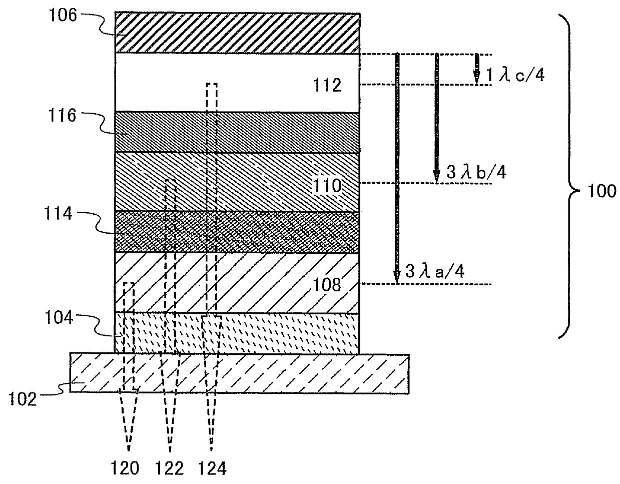
[0041]In this embodiment, an example of a structure of a light-emitting element will be described with reference to FIG. 1.

[0042]A light-emitting element 100 illustrated in FIG. 1 includes a light-transmitting electrode 104 and a light-reflecting electrode 106, and further a first light-emitting layer 108, a second light-emitting layer 110, a third light-emitting layer 112, a first intermediate layer 114, and a second intermediate layer 116 between the light-transmitting electrode 104 and the light-reflecting electrode 106. The first light-emitting layer 108 is located between the light-transmitting electrode 104 and the first intermediate layer 114. The second light-emitting layer 110 is located between the first intermediate layer 114 and the second intermediate layer 116. The third light-emitting layer 112 is located between the second intermediate layer 116 and the light-reflecting electrode 106. Note that the first light-emitting layer 108, the second light-emitti...

embodiment 2

(Embodiment 2)

[0065]In this embodiment, an example of a structure of a light-emitting element will be described with reference to FIG. 1. In this embodiment, a specific structure of the light-emitting element 100 illustrated in FIG. 1 and described in Embodiment 1 will be described.

[0066]As described in Embodiment 1, the light-emitting element 100 illustrated in FIG. 1 is provided over a substrate 102, includes the light-transmitting electrode 104 and the light-reflecting electrode 106, and includes the first light-emitting layer 108, the second light-emitting layer 110, the third light-emitting layer 112, the first intermediate layer 114, and the second intermediate layer 116 between the light-transmitting electrode 104 and the light-reflecting electrode 106. The first light-emitting layer 108 is provided between the light-transmitting electrode 104 and the first intermediate layer 114. The second light-emitting layer 110 is provided between the first intermediate layer 114 and the...

embodiment 3

(Embodiment 3)

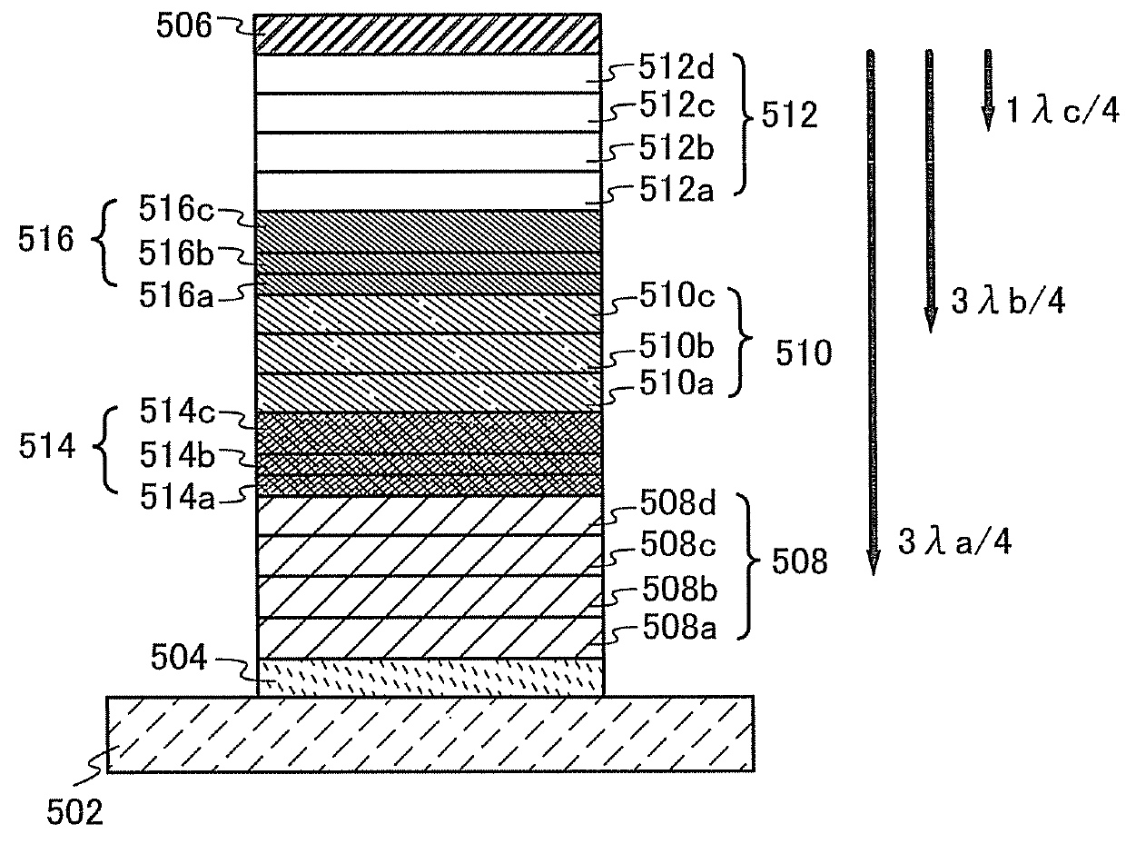
[0097]In this embodiment, a light-emitting element having a different structure from that of the light-emitting element in Embodiment 1 and Embodiment 2 will now be described with reference to FIG. 2.

[0098]The light-emitting element illustrated in FIG. 2 is provided over a substrate 502; includes a light-transmitting electrode 504 and a light-reflecting electrode 506; and includes, between the light-transmitting electrode 504 and the light-reflecting electrode 506, a first light-emitting layer 508 including a hole-injection layer 508a, a hole-transport layer 508b, a light-emitting layer 508c, and an electron-transport layer 508d; a first intermediate layer 514 including an electron-injection buffer layer 514a, an electron-relay layer 514b, and a charge-generation layer 514c; a second light-emitting layer 510 including a hole-transport layer 510a, a light-emitting layer 510b, and an electron-transport layer 510c; a second intermediate layer 516 including an electron-inj...


PUM


Abstract

To improve power efficiency of a light-emitting element for white emission even when light in a wavelength range of low luminosity is utilized. As a light-emitting element for white emission, three light-emitting layers are stacked. In such a light-emitting element, the three light-emitting layers are included between a light-transmitting electrode and a light-reflecting electrode, and light emitted from each light-emitting layer is reflected on the light-reflecting electrode and is transmitted through the light-transmitting electrode. In addition, the light-emitting layer closer to the light-reflecting electrode has a shorter optical path length. Thus, the position of each light-emitting layer is limited depending on the distance from the light-reflective electrode, and the optical path length of each light-emitting layer is adjusted; therefore the light-emitting element with high power efficiency can be provided.

Description

TECHNICAL FIELD[0001]One embodiment of the present invention relates to light-emitting elements that utilize electroluminescence. Further, one embodiment of the present invention relates to light-emitting devices or lighting devices which includes the light-emitting elements.BACKGROUND ART[0002]In recent years, research and development have been actively conducted on light-emitting elements utilizing electroluminescence. In a basic structure of the light-emitting element utilizing electroluminescence, a layer containing a light-emitting substance (hereinafter, the layer is referred to as a “light-emitting layer”) is sandwiched between a pair of electrodes. By applying voltage between the electrodes of the light-emitting element, light can be emitted from the light-emitting substance.[0003]Among light-emitting elements utilizing electroluminescence, a light-emitting element in which an organic compound is used as a light-emitting substance can be formed by stacking thin films. Thus, ...

Claims


Application Information

Patent Timeline
Patent Type & Authority Patents(United States)
IPC IPC(8): H05B33/00H01L51/50H01L51/00
CPCH01L51/5044H01L51/006H01L51/0061H01L51/0074H01L51/0085H01L2251/5376H01L2251/558H10K85/636H10K85/633H10K85/6576H10K85/342H10K50/131H10K50/852H10K2101/27H10K2102/351
Inventor SEO, SATOSHIUSHIKUBO, TAKAHIRO
Owner SEMICON ENERGY LAB CO LTD
Why Eureka
Try Eureka