
Vibrating member attachment structure

a technology of attachment structure and vibration member, which is applied in the direction of vibration dampers, shock absorbers, mechanical devices, etc., can solve the problems of increasing the number of parts, reducing the service life of the vibration member, so as to achieve a simple structure and reduce the probability of losing resilien

Active Publication Date: 2016-02-23
SUMITOMO RIKO CO LTD
View PDF18 Cites 0 Cited by
  • Summary
  • Abstract
  • Description
  • Claims
  • Application Information

AI Technical Summary

Benefits of technology

The present invention provides a vibrating member attachment structure that has a simple and minimal number of parts. Additionally, this structure is less likely to lose its resilience over time.

Problems solved by technology

However, this combination increases the number of parts such as the damper members and the shock absorption washers, and also complicates the structure.
This may cause loss of resilience.

Method used


Image

  • Vibrating member attachment structure
  • Vibrating member attachment structure
  • Vibrating member attachment structure

Examples


first embodiment

Configuration of Vibrating Member Attachment Structure

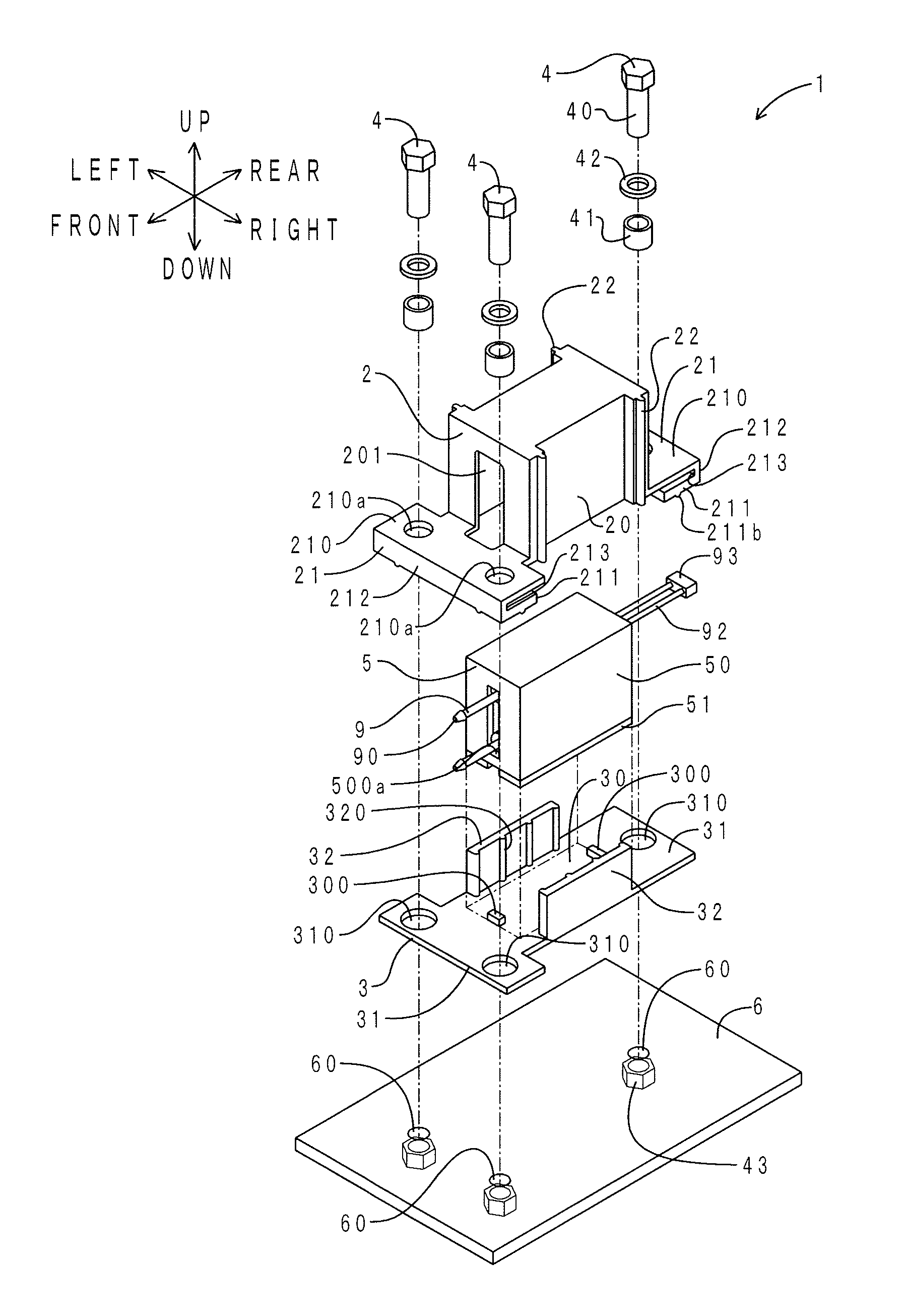
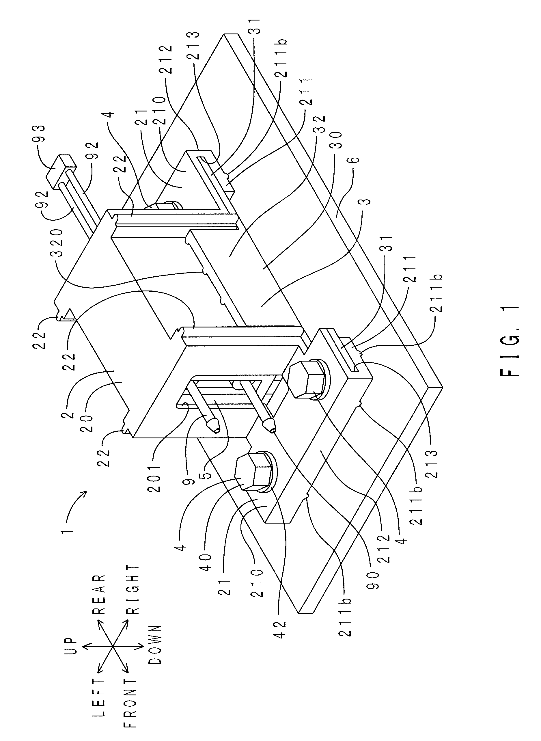
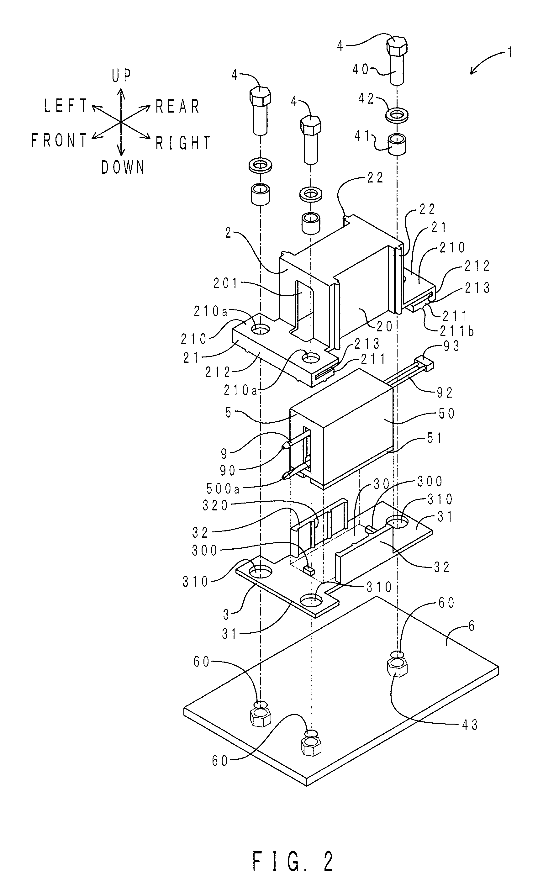
[0049]First, the configuration of a vibrating member attachment structure of the present embodiment will be described. FIG. 1 is a perspective view of the vibrating member attachment structure of the present embodiment. FIG. 2 is an exploded perspective view of the vibrating member attachment structure. FIG. 3 is an exploded perspective view of a portion near a sound absorption layer of the vibrating member attachment structure. FIG. 4 is a sectional view along the direction IV-VI in FIG. 5 (a longitudinal sectional view as viewed from the right). FIG. 5 is a sectional view taken along the direction V-V in FIG. 4 (a longitudinal sectional view as viewed from above).

[0050]As shown in FIGS. 1 to 5, a vibrating member attachment structure 1 of the present embodiment is used to attach an electromagnetic valve 9 to a bracket 6. The electromagnetic valve 9 is included in the concept of the “vibrating member” of the present invention. T...

second embodiment

[0104]A vibrating, member attachment structure of the present embodiment is different from the vibrating member attachment structure of the first embodiment in that the folded-back portions of the sound insulation layer have through grooves, the sound insulation layer has two shift suppressing walls, the insertion portions of the support member have through grooves, and the contact portions have no line contact portion. Only the differences will be described below.

[0105]FIG. 6 is an exploded perspective view of the vibrating member attachment structure of the present embodiment. Portions corresponding to those of FIG. 2 are denoted by the same reference characters. As shown in FIG. 6, U-shaped through grooves 214 are formed in the pair of front and rear folded-back portions 21. Each through groove 214 extends from the hem portion 210 to the contact portion 211 via the joint portion 212. The bolt 40 and the collar 41 are inserted through the through groove 214. The through groove 214...


PUM


Abstract

A vibrating member attachment structure includes: a sound insulation layer made of elastomer and including an accommodating portion that defines an accommodating space in which a vibrating member is accommodated, and a folded-back portion having a hem portion connecting to the accommodating portion, a contact portion placed so as to face the hem portion and contacting a mating member, a joint portion connecting the hem portion and the contact portion, and an insertion space defined by the hem portion, the contact portion, and the joint portion; a support member having higher rigidity than the sound insulation layer and including a sealing portion that seals an opening of the accommodating space, and an insertion portion that connects to the sealing portion and that is inserted in the insertion space; and an attachment member and including a shaft portion and a deformation suppressing portion.

Description

CLAIM FOR PRIORITY[0001]This application is a Continuation of PCT / JP2013 / 065561 filed Jun. 5, 2013, and claims the priority benefit of Japanese application 2012-130733, filed Jun. 8, 2012, the contents of which is expressly incorporated by reference herein in its entirety.TECHNICAL FIELD[0002]The present invention relates to vibrating member attachment structures that are used to attach a vibrating member such as an electromagnetic valve or a servomotor to a mating member.BACKGROUND ART[0003]Patent Document 1 discloses a damping device having a floating structure. As shown in paragraph [0039] and [FIG. 2] in Patent Document 1, the damping device elastically supports an electronic device with respect to a case body in a non-contact state. The damping device includes damper members and shock absorbing member washers. The damper members and the shock absorbing member washers are made of an elastomer (e.g., a gel-like resin).[0004]Patent Document 2 discloses a soundproof cover for exhau...

Claims


Application Information

Patent Timeline
Patent Type & Authority Patents(United States)
IPC IPC(8): F16F7/00F16F15/08
CPCF16F7/00F16F15/08
Inventor TOMIYAMA, KOJIYABU, AKIO
Owner SUMITOMO RIKO CO LTD
Learn More