Rotation tool

Inactive Publication Date: 2016-03-01
WERVIA LLC
View PDF11 Cites 0 Cited by
  • Summary
  • Abstract
  • Description
  • Claims
  • Application Information

AI Technical Summary

Benefits of technology

[0008]Next, the person would position the tool such that the engaging member is in contact with the rotatable object to be tested. The engaging member may already be rotating before contact or the rotation may begin after contact. Then, the engaging member imparts rotation to the tested object. The tested object will then rotate at a speed directed by the person. This allows the person to observe the rotation of the tested object, as well as any consequences of that rotat

Problems solved by technology

Often, these rotatable objects are difficult to selectively rotate.
However, these pulleys are difficult to reach, are interconnected by belts and are not independently powered.
Therefore, it is very difficult to independently test each pulley.
The first approach causes the pulleys to rotate at operational speeds but confounds identifying a specific

Method used


Image

  • Rotation tool
  • Rotation tool
  • Rotation tool

Examples


Embodiment Construction

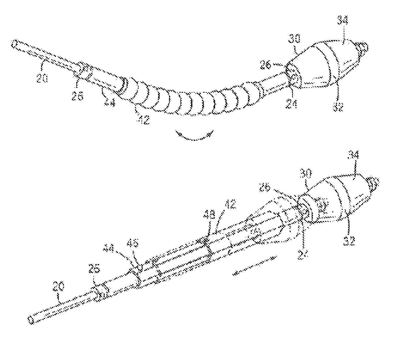
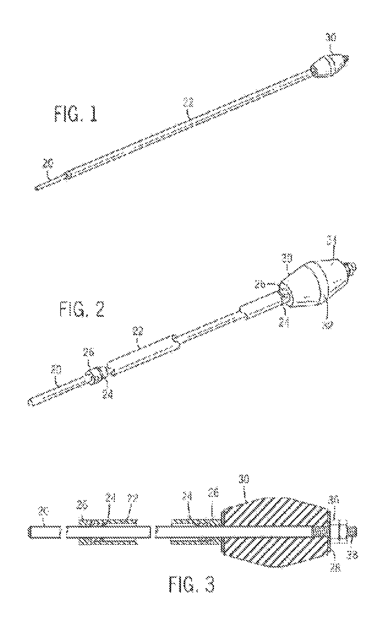
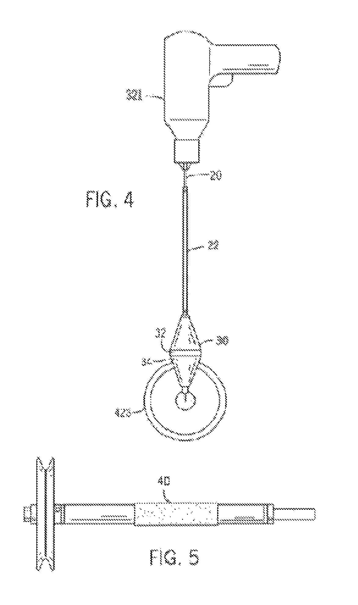
[0022]The tool is used to impart rotation to a selected, rotatable item. The tool has an engagement member 30 that imparts rotation onto the selected item 423. The engagement member 30 can be in a variety of forms including, but not limited to, a solid drum as shown in FIG. 1 and FIG. 3, a smooth drum (FIG. 6), grooved drum (FIG. 5), or any other suitable shape that an average person skilled in the arts would recognize as functional.

[0023]The engagement member 30 rotates due to a rotation source 321 imparting a rotation. Once the rotation source 321 imparts rotation on the shaft 20 which then transfers to the engagement member 30, the engagement member 30 then can cause rotation in a selected item 423 either through direct contact as shown in FIG. 4 or through an intermediary such as a belt 18 as shown in FIG. 8.

[0024]As shown in FIG. 7 the rotation source 321 can be housed closer to or inside the engagement member 30 and is directly powered either through an independent or internal...


PUM


Abstract

A tool for assessing rotatable objects in an engine by selectively imparting a rotation to a chosen number of the rotatable objects that includes an engagement member, a shaft portion, and a motor as a rotation source. In the preferred embodiment, the engagement member mounted on a first end of the shaft engages the rotatable object. A support member means is mounted on a second end of the extendable member or on the shaft. A rotation source is used to impart rotation on shaft and engagement member and thus to the rotatable object to be rotated as may be required to facilitate for the testing and adjustment procedures to be performed upon the rotatable member.

Description

FIELD OF INVENTION[0001]The tool relates generally to an apparatus to test rotatable objects. In a preferred form, the present tool relates to an apparatus to assess rotatable objects in an engine.BACKGROUND OF THE INVENTION[0002]The disclosed tool is used to engage a selected, rotatable object encountered by those working on machinery. Often, these rotatable objects are difficult to selectively rotate. For example, in an automobile engine, a pulley may need to be rotated to identify which individual pulley is failing or exhibiting signs of failure. However, these pulleys are difficult to reach, are interconnected by belts and are not independently powered. Therefore, it is very difficult to independently test each pulley. Currently, one must attempt to either have the engine running and thus powering all the connected pulleys or attempt to rotate the pulleys by hand. The first approach causes the pulleys to rotate at operational speeds but confounds identifying a specific problem d...

Claims


Application Information

Patent Timeline
IPC IPC(8): B25B33/00
CPCB25B33/00
Inventor CHRISTENSEN, WALTER, M.
Owner WERVIA LLC
Why Eureka
Try Eureka