Axial-flow machine having a dimensionally stable assembly

a technology of axial flow machine and assembly, which is applied in the direction of dynamo-electric machines, electrical apparatus, magnetic circuits, etc., can solve the problems of increasing, among other factors, the manufacturing cost of axial flow machines

Active Publication Date: 2022-07-26
MIBA SINTER AUSTRIA
View PDF18 Cites 0 Cited by
  • Summary
  • Abstract
  • Description
  • Claims
  • Application Information

AI Technical Summary

Problems solved by technology

Disadvantageously, relatively broad dimensions are needed on the spoked wheel for the interlocking ability of the subassembly—which restricts the size fraction of the permanent magnets on the rotor and thus the motor power of the axial-flow machine.
The...

Method used


Image

  • Axial-flow machine having a dimensionally stable assembly
  • Axial-flow machine having a dimensionally stable assembly

Examples


Embodiment Construction

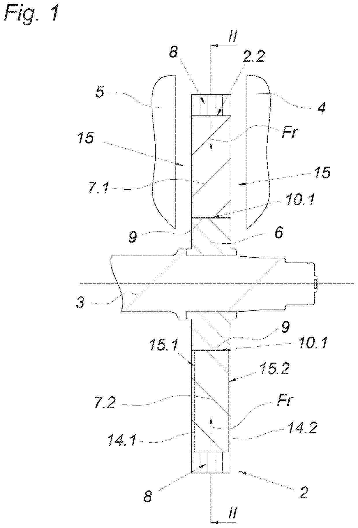
[0024]The axial-flow machine 1 illustrated by way of example according to FIG. 1 has a rotor 2, a machine shaft 3 and two stators 4, 5 disposed on both sides of the rotor 2. The rotor 2 is fastened on the machine shaft 3—and specifically via its rotor hub 6 held frictionally on the machine shaft 3. In addition, permanent magnets 7.1, 7.2, which are disposed circularly around the machine shaft 3, are associated with the rotor 2.

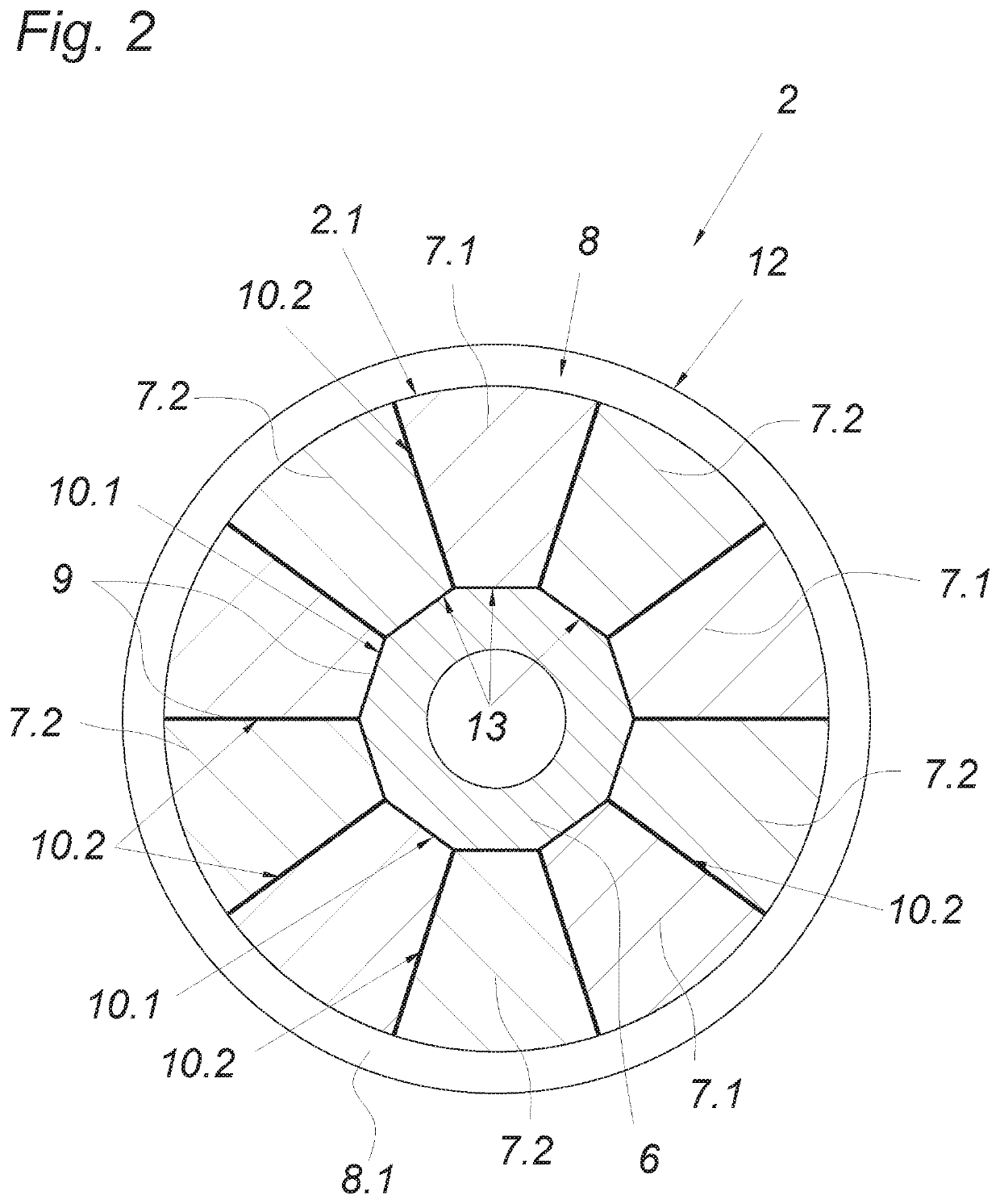
[0025]The permanent magnets 7.1, 7.2 are alternately magnetized—to the effect, for example, that two adjacent permanent magnets have opposite directions of magnetization, as illustrated by a different shading pattern according to FIG. 2. The magnetization directions of the permanent magnets 7.1, 7.2 run parallel to the longitudinal axis of the machine shaft 3.

[0026]In addition, the rotor 2 has a bracing means 8 disposed on the outer circumference 2.1 of the rotor 2 and encircling it in closed manner. This bracing means 8, designed as a bandage 8.1, consists of...


PUM


Abstract

An axial-flow machine has a dimensionally stable assembly, a machine shaft, a rotor fastened on the machine shaft and provided with a rotor hub, permanent magnets disposed circularly around the machine shaft, an adhesive and a brace, which is disposed on the outer circumference of the rotor and encircles it in closed manner and which urges the permanent magnets with a radially inwardly directed tension force, and stators disposed on both sides of the rotor. The permanent magnets are seated on the rotor hub via first adhesive joints equipped with adhesive and adjoin one another via second adhesive joints equipped with adhesive, wherein the permanent magnets, the rotor hub, the brace and the adhesive form the dimensionally stable assembly, the radial and axial dimensional stability of which is determined substantially by the radial tension force of the brace on the permanent magnets.

Description

CROSS REFERENCE TO RELATED APPLICATIONS[0001]Applicant claims priority under 35 U.S.C. § 119 of European Application No. 17199947.7 filed on Nov. 3, 2017, the disclosure of which is incorporated by reference.BACKGROUND OF THE INVENTION1. Field of the Invention[0002]The invention relates to an axial-flow machine having a dimensionally stable assembly, having a machine shaft, having a rotor fastened on the machine shaft and provided with a rotor hub, permanent magnets disposed circularly around the machine shaft, an adhesive and a bracing means, which is disposed on the outer circumference of the rotor and encircles it in closed manner and which urges the permanent magnets with a radial tension force, and having stators disposed on both sides of the rotor.2. Description of the Related Art[0003]In order to construct a rotor of an axial-flow machine having low mass and inertia, it known from the prior art (EP1203436A1) to create a kind of spoked wheel of fiber-reinforced plastic, in whi...

Claims


Application Information

Patent Timeline
IPC IPC(8): H02K1/2793H02K1/2713H02K16/04H02K21/24
CPCH02K1/2793H02K1/2713H02K16/04H02K21/24H02K1/2796
Inventor SANDNER, CHRISTIANANDESSNER, DIETMARKOBLER, RALFREDL, MATTHIASNAGLSTRASSER, MARKUS
Owner MIBA SINTER AUSTRIA
Why Eureka
Try Eureka