Electric door-locking apparatus, and electric door comprising same

a technology of electric door locks and electric doors, which is applied in the direction of electrical locking circuits, wing accessories, lock applications, etc., can solve the problems of increased fabrication and maintenance costs, dangerous situations, etc., and achieves the effect of reducing the danger of failure and operation errors, simple structure, and easy fabrication and maintenan

Inactive Publication Date: 2014-03-04
THE KOREA DEV BANK
View PDF46 Cites 5 Cited by
  • Summary
  • Abstract
  • Description
  • Claims
  • Application Information

AI Technical Summary

Benefits of technology

[0011]Accordingly, the present invention has been made keeping in mind the above problems occurring in the related art, and the present invention is intended to propose to an electric door lock which has a simple structure, ensures the reliability of a locking function, reduces a danger of a failure and an operation error, and is easy to fabricate and maintain, saving the cost for the fabrication and maintenance relative to the cost taken in the related art, and an electric door having the same.
[0025]As set forth before, the electric door lock has a simple structure, ensures the reliability of a locking function, reduces a danger of a failure and an operation error, and is easy to fabricate and maintain, saving the cost for the fabrication and maintenance relative to the cost taken in the related art.

Problems solved by technology

However, if the situation is that the railway train is running, or the state of the railway tracks is dangerous, or otherwise if nevertheless the situation is not an emergency state, the passengers can open the electric door even with their less effort, a very dangerous situation can be caused.
However, the conventional electric door lock having the above-mentioned configuration has a problem of increased cost of fabrication and maintenance because of numerous, complex parts.

Method used


Image

  • Electric door-locking apparatus, and electric door comprising same
  • Electric door-locking apparatus, and electric door comprising same
  • Electric door-locking apparatus, and electric door comprising same

Examples


Embodiment Construction

[0032]Reference will now be made in greater detail to a preferred embodiment of the invention, an example of which is illustrated in the accompanying drawings. Wherever possible, the same reference numerals will be used throughout the drawings and the description to refer to the same or like parts.

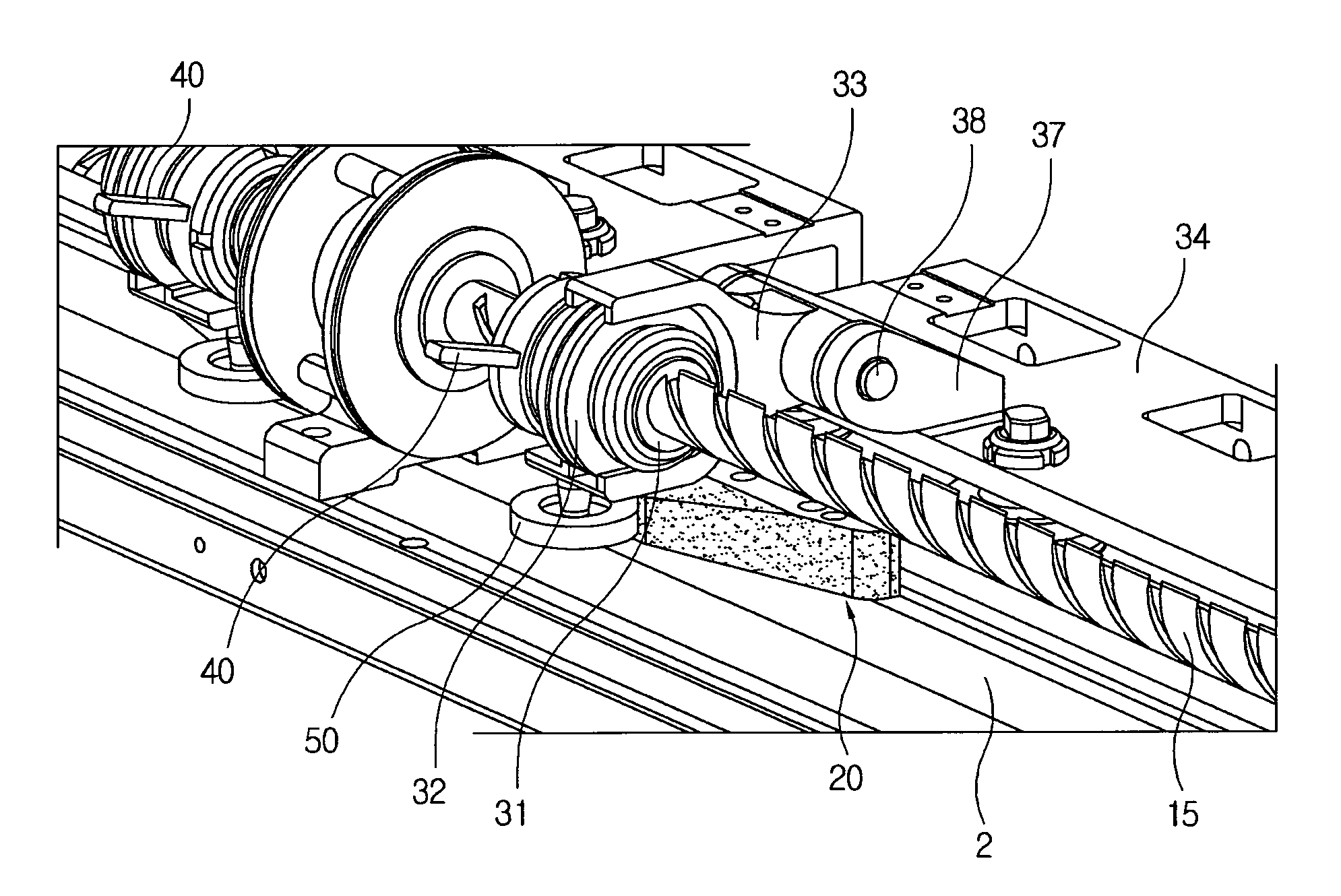
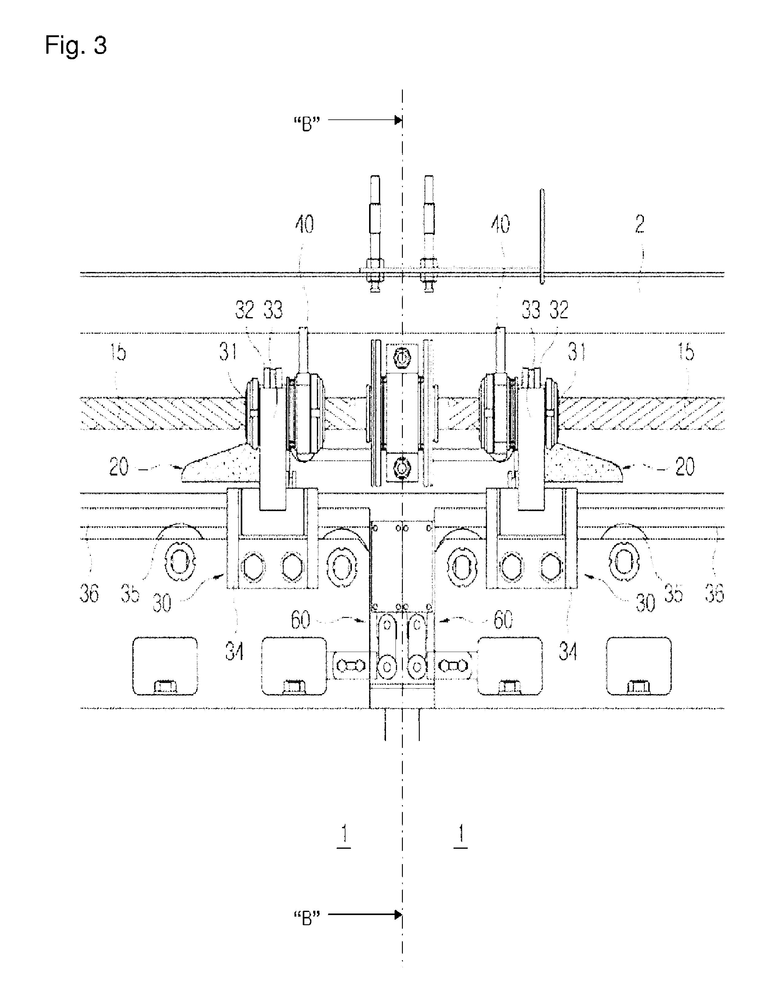
[0033]FIG. 1 is a partially enlarged perspective view of an embodiment of an electric door lock that is viewed from upside, FIG. 2 is a partially enlarged perspective view of a major part of the electric door lock that is viewed in the direction A of FIG. 1, FIG. 3 is a front view of the electric door lock, FIG. 4 is a view of the electric door lock that is viewed in line B-B of FIG. 3, and FIG. 5 is a view that is partially cut from FIG. 3 to explain the operation of a locking roller of the electric door lock.

[0034]As shown in FIGS. 1 to 5, the electric door lock includes a locking switch 10 provided in a door frame 2 for checking the locking state of a door body 1 when the door body is c...


PUM


Abstract

The present invention provides an electric door-locking apparatus, and an electric door comprising same. The electric door-locking apparatus according to the present invention comprises: a locking switch arranged at a door frame to check the locked status of an electric door body when the electric door body is closed; a screw rotatable in the forward and backward directions; a locking roller guide arranged at the door frame in the vicinity of the screw; and a sliding unit, one end of which is rotatably connected to the screw and the other end of which is connected to the electric door body. The electric door-locking apparatus according to the present invention has a structure which enables simple and easy operation, improves the reliability of the locking function, reduces the risk of failure and erroneous operation, and enables easy manufacture and maintenance to reduce manufacturing costs and maintenance costs as compared to conventional apparatuses.

Description

CROSS REFERENCE TO RELATED APPLICATION[0001]This application claims the priority of Korean Patent Application No. 10-2009-0024908, filed on Mar. 24, 2009, in the KIPO (Korean Intellectual Property Office), the disclosure of which is incorporated herein in their entirety by reference. Further, this application is the National Phase application of International Application No. PCT / KR2010 / 001817, filed Mar. 24, 2010, which designates the United States and was published in Korean. Each of these applications is hereby incorporated by reference in their entirety into the present application.BACKGROUND OF THE INVENTION[0002]1. Field of the Invention[0003]The present invention relates, in general, to an electric door lock and an electric door having the same and, more particularly, to an electric door lock which has a simple structure, ensures the reliability of a locking function, reduces a danger of a failure and an operation error, and is easy to fabricate and maintain, saving the cost f...

Claims


Application Information

Patent Timeline
Patent Type & Authority Patents(United States)
IPC IPC(8): E06B3/70E05B47/00E05B65/08
CPCE05B2047/0068E05Y2201/232E05F15/148E05B81/00E05B83/02E05Y2201/22E05B81/70E05B83/363E05F15/652Y10T70/5155
Inventor KONG, YOU-SANG
Owner THE KOREA DEV BANK
Why Eureka
Try Eureka