
Self-capacitive touch panel

a touch panel and self-capacitive technology, applied in capacitance measurement, resistance/reactance/impedence, instruments, etc., can solve the problems of large error in the calculation of coordinates x and y, encountering a great challenge, etc., and achieve the effect of preferred accuracy

Active Publication Date: 2016-03-01
ILI TECHNOLOGY CORPORATION
View PDF9 Cites 5 Cited by
  • Summary
  • Abstract
  • Description
  • Claims
  • Application Information

AI Technical Summary

Benefits of technology

The invention is a new type of touch panel that can detect user touch more accurately than previous designs. This is achieved by adding more sensors to the border regions of the touch panel, allowing for a more precise sensing result.

Problems solved by technology

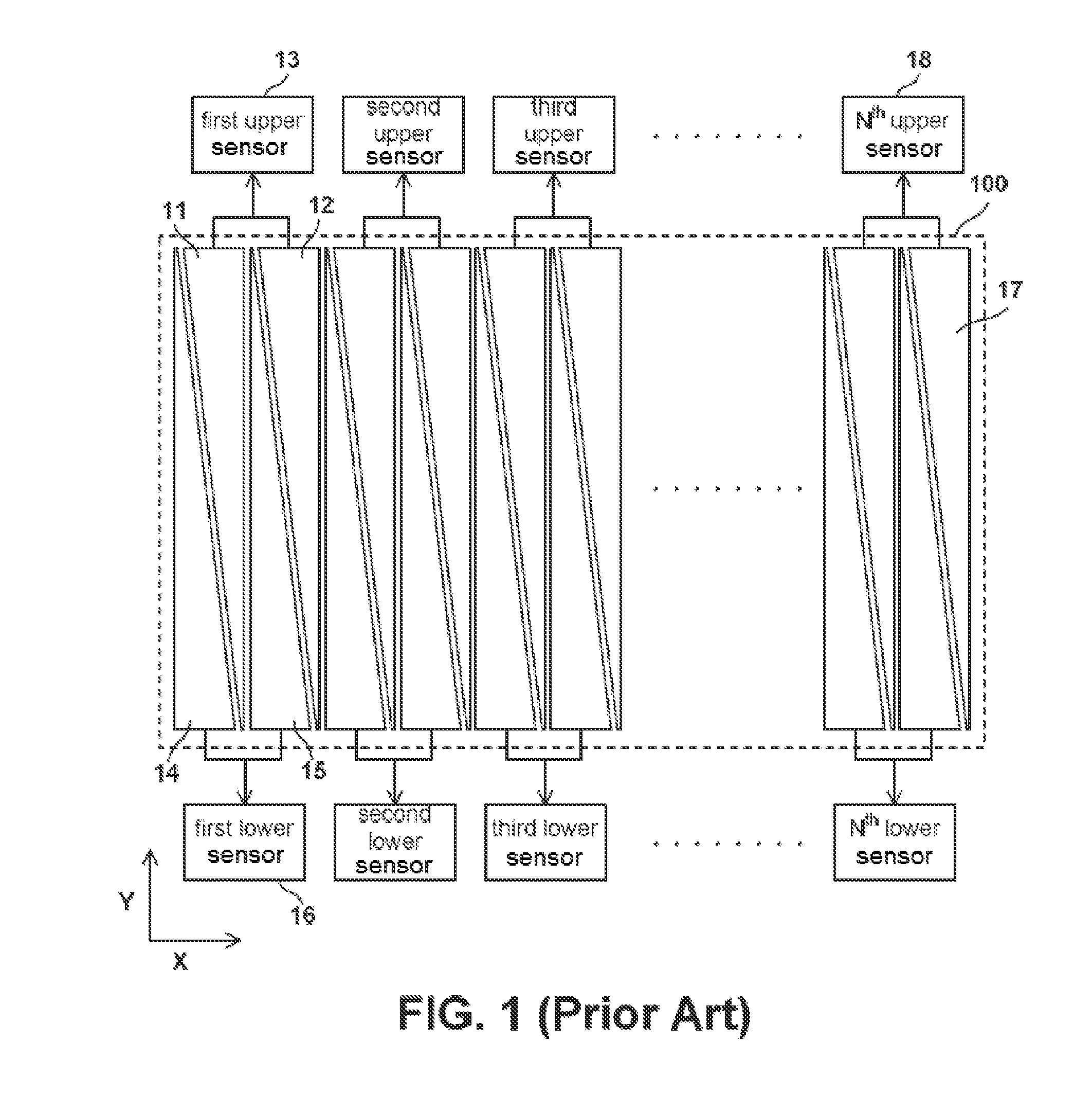
However, the touch panel in FIG. 1 encounters a great challenge—errors in the sensing results of the left and right borders are extremely large.
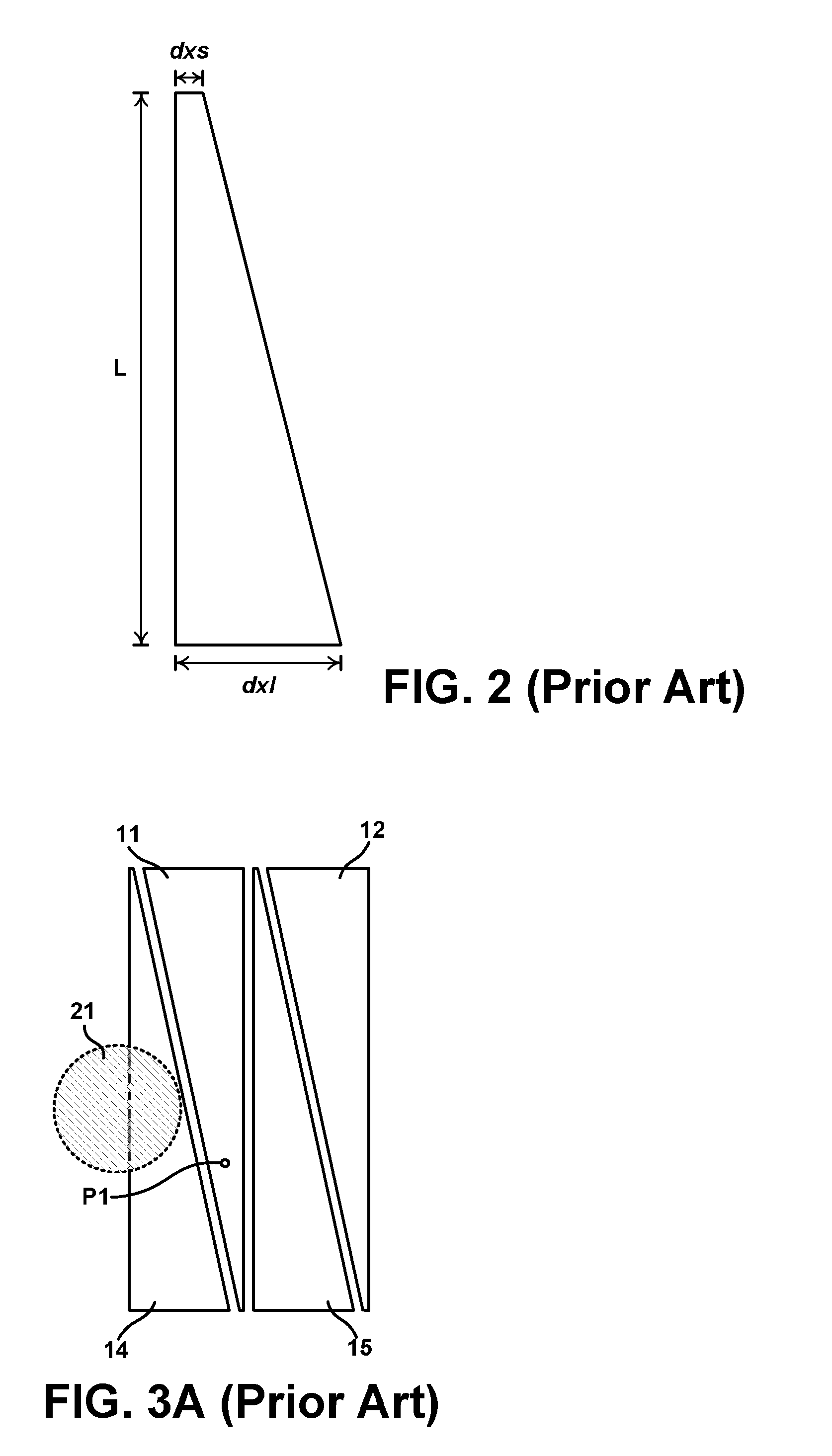
However, substantially errors exist in the coordinates x and y calculated based on the capacitance change sensed by the first lower sensor 16.
It is obvious that the above calculation does not correctly respond the Y coordinate of the touch position.
Under the circumstances, only the Nth upper sensor senses the capacitance change, such that a substantially error also exists in the coordinates of the touch position calculated accordingly.
The above issue of sensing errors in the border regions likely leads the controller to misjudge a real intention of a user touch to further trigger incorrect operation result.
However, if the left and right border regions of the sensing area 100 are neglected to avoid the above issue, hardware costs are wasted.

Method used


Image

  • Self-capacitive touch panel
  • Self-capacitive touch panel
  • Self-capacitive touch panel

Examples


Embodiment Construction

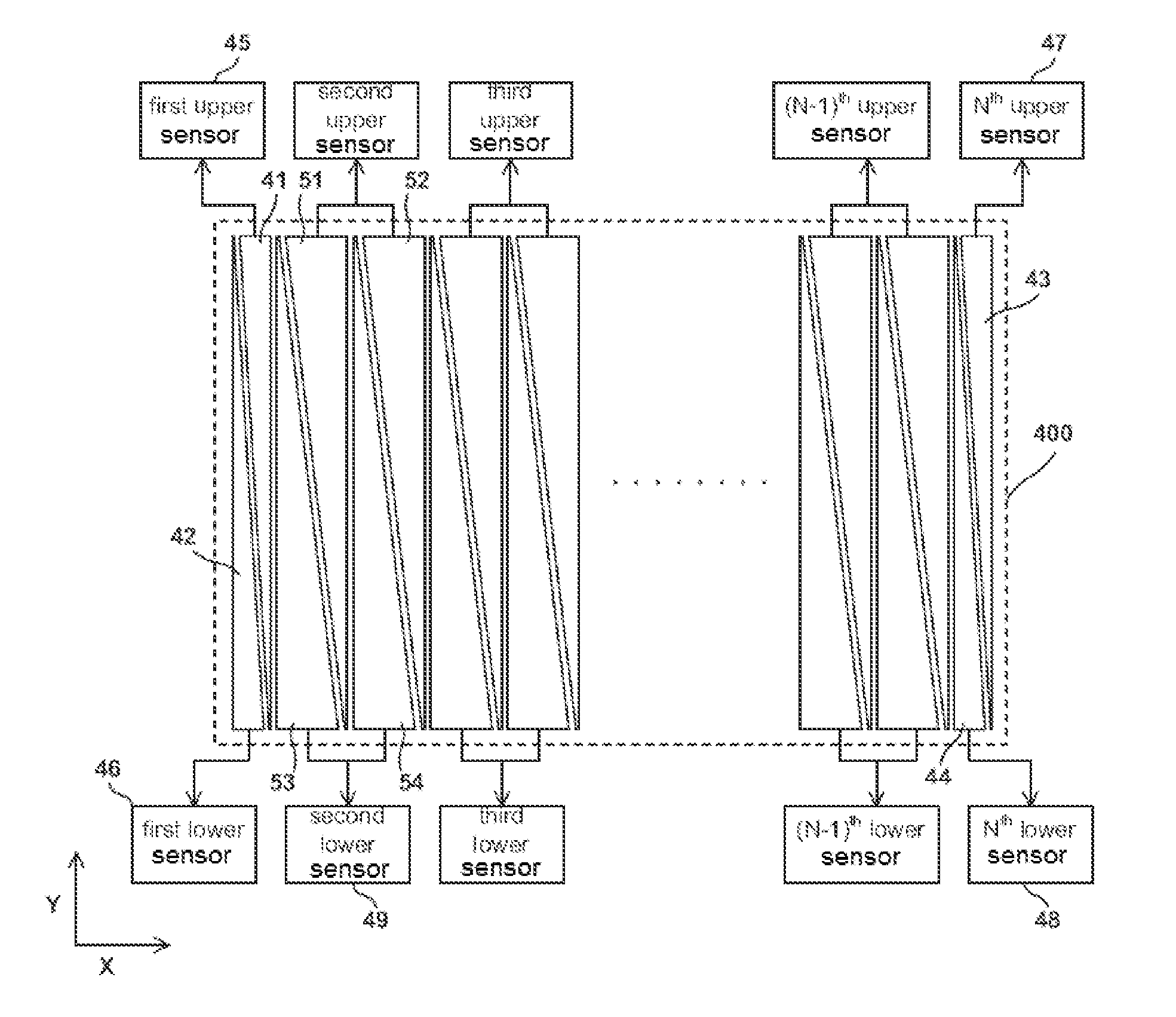
[0032]FIG. 4 shows a function block diagram of a self-capacitive touch panel according to an embodiment of the present invention. Multiple electrodes appearing similar to right triangles are provided within a sensing area 400 demarcated by a dotted frame. In practice, the shapes of the electrodes may be identical to the tall and narrow trapezoids as shown in FIG. 2. Referring to FIG. 4, in the sensing area 400, leftmost border electrodes 41 and 42 as well as rightmost border electrodes 43 and 44 are narrower than other electrodes (e.g., electrodes 51, 52, 53 and 54) in a central region. In other words, distinct from the prior art shown in FIG. 1, not all the electrodes in this embodiment are equal in width. The border electrodes 41, 42, 43 and 44 are similar to a first right triangle, whereas other electrodes are similar to a second right triangle. The shortest side (parallel to the X direction in the diagram) of the first right triangle is shorter than the shortest side of the seco...


PUM


Abstract

A self-capacitive touch panel including a border region and a central region is provided. The border region has a first area and corresponds to a P number of first sensors. The central region has a second area and corresponds to a Q number of second sensors. A ratio of P to the first area is greater than a ratio of Q to the second area.

Description

[0001]This application claims the benefit of Taiwan application Serial No. 101126736, filed Jul. 25, 2012, the subject matter of which is incorporated herein by reference.BACKGROUND OF THE INVENTION[0002]1. Field of the Invention[0003]The invention relates in general to a touch system, and more particularly, to a technique for enhancing the accuracy in sensing results of a border region of a touch panel.[0004]2. Description of the Related Art[0005]Operating interfaces of recent electronic products are becoming increasingly user-friendly and intuitive. For example, through a touch screen, a user can directly interact with applications as well as input messages / texts / patterns with fingers or a stylus, thus eliminating complications associated with other input devices such as a keyboard or buttons. In practice, a touch screen usually comprises a touch panel and a display provided at the back of the touch panel. According to a touch position on the touch panel and a currently displayed ...

Claims


Application Information

Patent Timeline
Patent Type & Authority Patents(United States)
IPC IPC(8): G01R27/26G06F3/044
CPCG06F3/044G01R27/2605G06F3/0443G06F3/0448
Inventor LIU, CHUN-CHENTSAI, MENG-CHE
Owner ILI TECHNOLOGY CORPORATION
Learn More