
Touch device

a touch device and touch technology, applied in the field of electronic devices, can solve the problems of poor touch input sensing ability of the touch device, the inability of the conventional human-to-machine interface using the keyboard to meet the demands of users, etc., and achieve the effect of preventing the negative effect of the wiring line on the correctness of the touch sensing, reducing the resistance of the longer wiring line in the patterned electrode set, and avoiding the negative effect of the wiring lin

Active Publication Date: 2015-04-21
CORETRONIC
View PDF7 Cites 4 Cited by
  • Summary
  • Abstract
  • Description
  • Claims
  • Application Information

AI Technical Summary

Benefits of technology

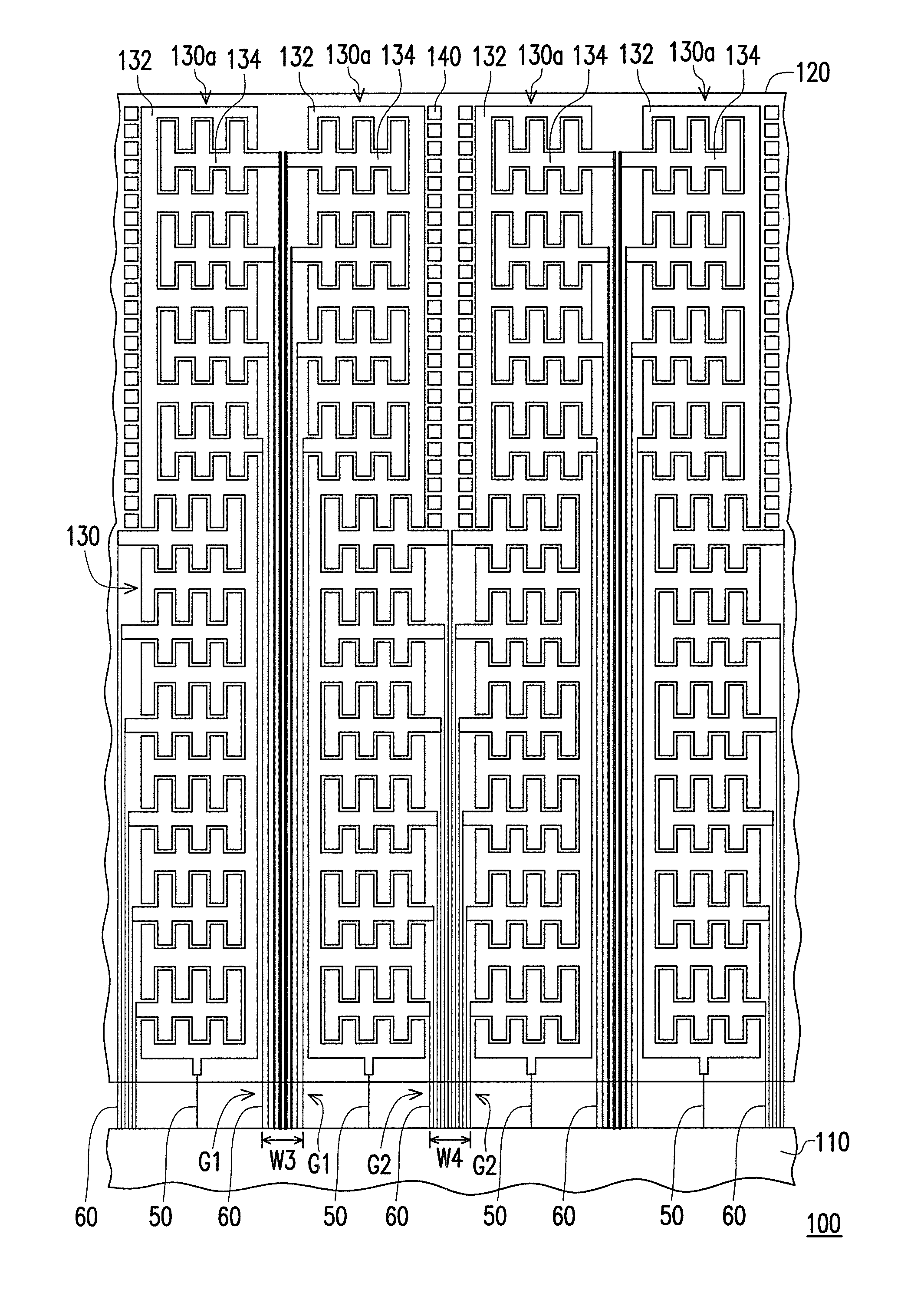
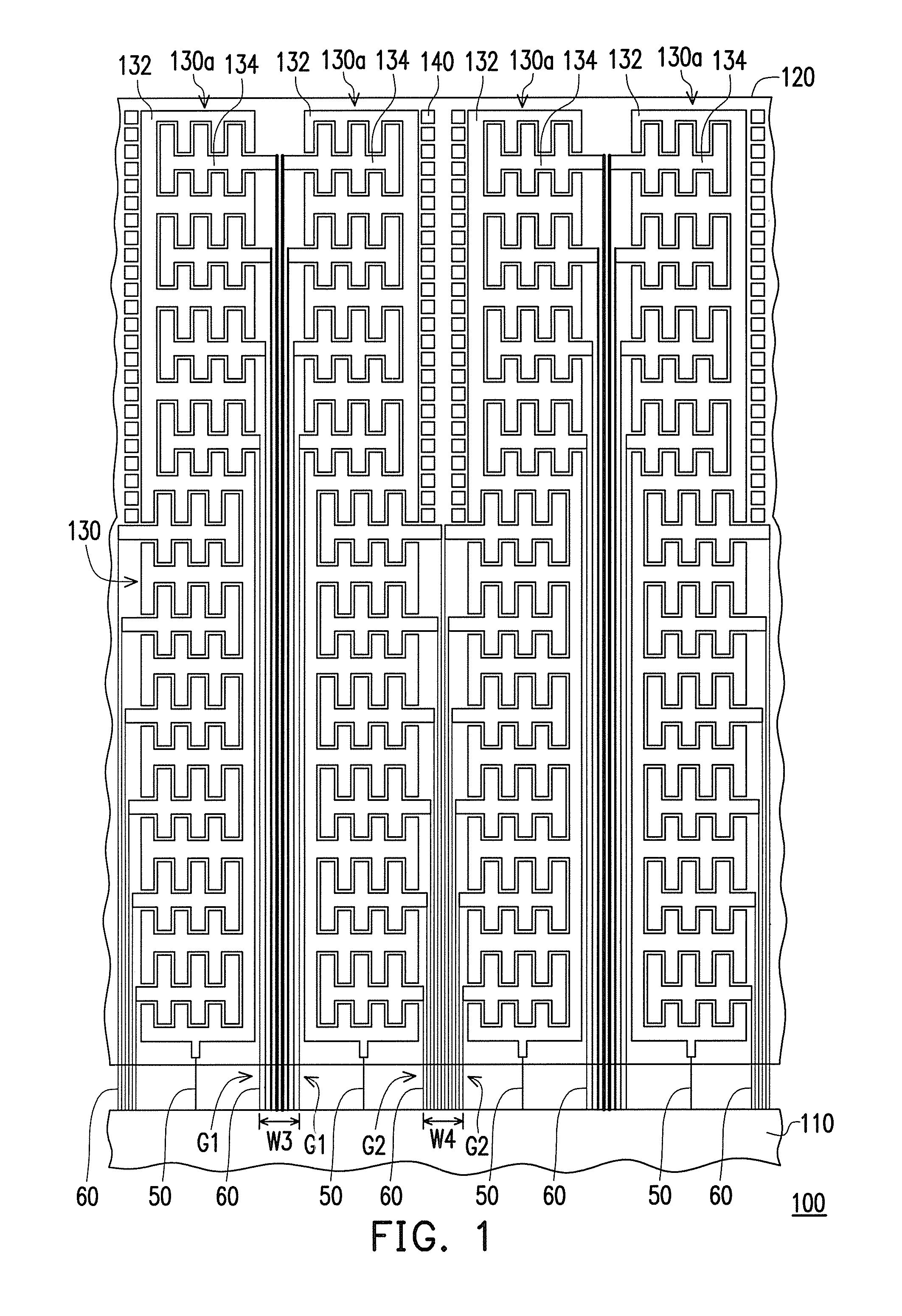
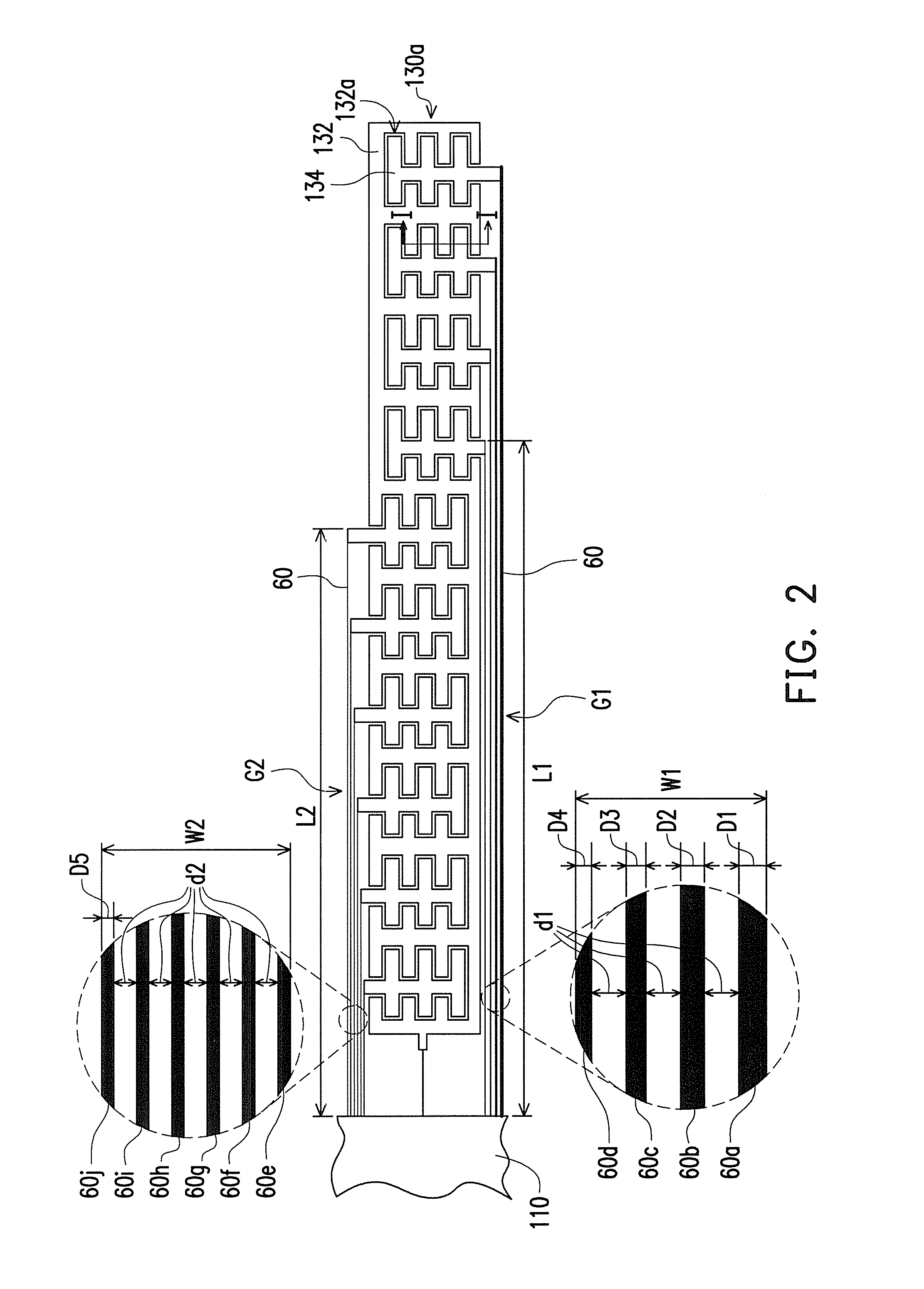
The invention provides a solution for reducing the resistance of longer wiring lines in a touch device. By divided the wiring lines into two groups and increasing their diameter, the resistance of the longer wiring lines is effectively reduced without affecting the correctness of transmitting the touch-sensing signal. The wiring lines are located in the same touch-sensing layer with the sensing electrodes and the driving electrode. The width of the non-sensing region constituted by the wiring lines of each group is the same, which prevents misjudgement of touch recognition system caused by inconsistent widths of the non-sensing regions. The invention achieves a preferable accuracy and efficiency.

Problems solved by technology

The conventional human-to-machine interface using keyboard is gradually incapable of meeting the demands from users, as electronic devices develop towards using multi-touch.
However, the touch input sensing ability of the touch device is poor due to the high surface resistance of the current electrode material such as indium tin oxide (ITO).

Method used


Image

  • Touch device
  • Touch device
  • Touch device

Examples


Embodiment Construction

[0027]In the following detailed description of the preferred embodiments, reference is made to the accompanying drawings which form a part hereof, and in which are shown by way of illustration specific embodiments in which the invention may be practiced. In this regard, directional terminology, such as “top,”“bottom,”“front,”“back,” etc., is used with reference to the orientation of the Figure(s) being described. The components of the present invention can be positioned in a number of different orientations. As such, the directional terminology is used for purposes of illustration and is in no way limiting. On the other hand, the drawings are only schematic and the sizes of components may be exaggerated for clarity. It is to be understood that other embodiments may be utilized and structural changes may be made without departing from the scope of the present invention. Also, it is to be understood that the phraseology and terminology used herein are for the purpose of description an...


PUM


Abstract

A touch device includes a circuit board, a substrate and a touch-sensing layer. The touch-sensing layer including patterned electrode sets is disposed on the substrate. Each patterned electrode set includes a driving electrode connected to the circuit board and sensing electrodes having wiring lines connected to the circuit board. The wiring lines of each patterned electrode set include first and second groups. The length for one of the wiring lines in the first group is greater than the length for one of the wiring lines in the second group. Diameters of the wiring lines in the first group are greater than diameters of the wiring lines in the second group. The diameter of the longer wiring line is greater than the diameter of the shorter wiring line, in the first group. The diameters in the second group are identical. The total widths of the first and second groups are equal.

Description

CROSS-REFERENCE TO RELATED APPLICATION[0001]This application claims the priority benefit of Taiwan application serial no. 102107929, filed on Mar. 6, 2013. The entirety of the above-mentioned patent application is hereby incorporated by reference herein and made a part of this specification.BACKGROUND[0002]1. Technical Field[0003]The invention relates to an electronic device, and more particularly, to a touch device.[0004]2. Related Art[0005]The conventional human-to-machine interface using keyboard is gradually incapable of meeting the demands from users, as electronic devices develop towards using multi-touch. Under such circumstances, touch devices have enjoyed burgeoning development. The operating method of touch devices could be more simple, convenient and intuitive, as compared to the operating method of the conventional operating interface using keyboard. Through the touch device, the user is capable of directly touching objects, menus or pictures on the screen with the finge...

Claims


Application Information

Patent Timeline
Patent Type & Authority Patents(United States)
IPC IPC(8): G06F3/041G06F3/047
CPCG06F3/047G06F3/0443G06F3/0448
Inventor LIU, YUNG-LUNGCHEN, HSIEN-MINGHWANG, CHWEN-TAY
Owner CORETRONIC
Learn More