
Head-up display device

a display device and head-up technology, applied in the direction of control devices, instruments, vehicle components, etc., can solve the problems that the number of times of reflection cannot be drastically extended, and the optical path length cannot be extended

Active Publication Date: 2018-10-04
HONDA MOTOR CO LTD
View PDF2 Cites 2 Cited by
  • Summary
  • Abstract
  • Description
  • Claims
  • Application Information

AI Technical Summary

Benefits of technology

The patent describes a structure that allows for a virtual image to be displayed in a vehicle room at a far position using a long optical path. By using the roof of the vehicle as a reflection position, the virtual image can be overlapped with the real world, providing intuitive information to the occupant. The structure allows for the optical path to be extended by changing the positions of reflectors, increasing the degree of freedom. The reflectors can be easily manufactured using a mirror with a concave or convex shape. The second reflector is attached more easily using this structure. Overall, the patent enables a more immersive virtual display in the vehicle room.

Problems solved by technology

However, if the projection unit itself is not large, increasing the number of times of reflection cannot extend the optical path length drastically.
On the other hand, increasing the size of the projection unit can extend the optical path length to some extent; however, the vehicle does not include a space for providing a large projection unit.

Method used


Image

  • Head-up display device
  • Head-up display device
  • Head-up display device

Examples


first embodiment

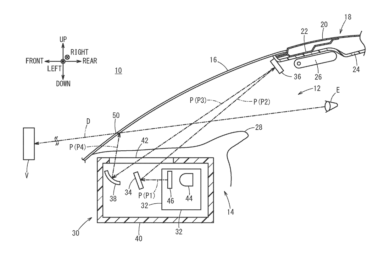
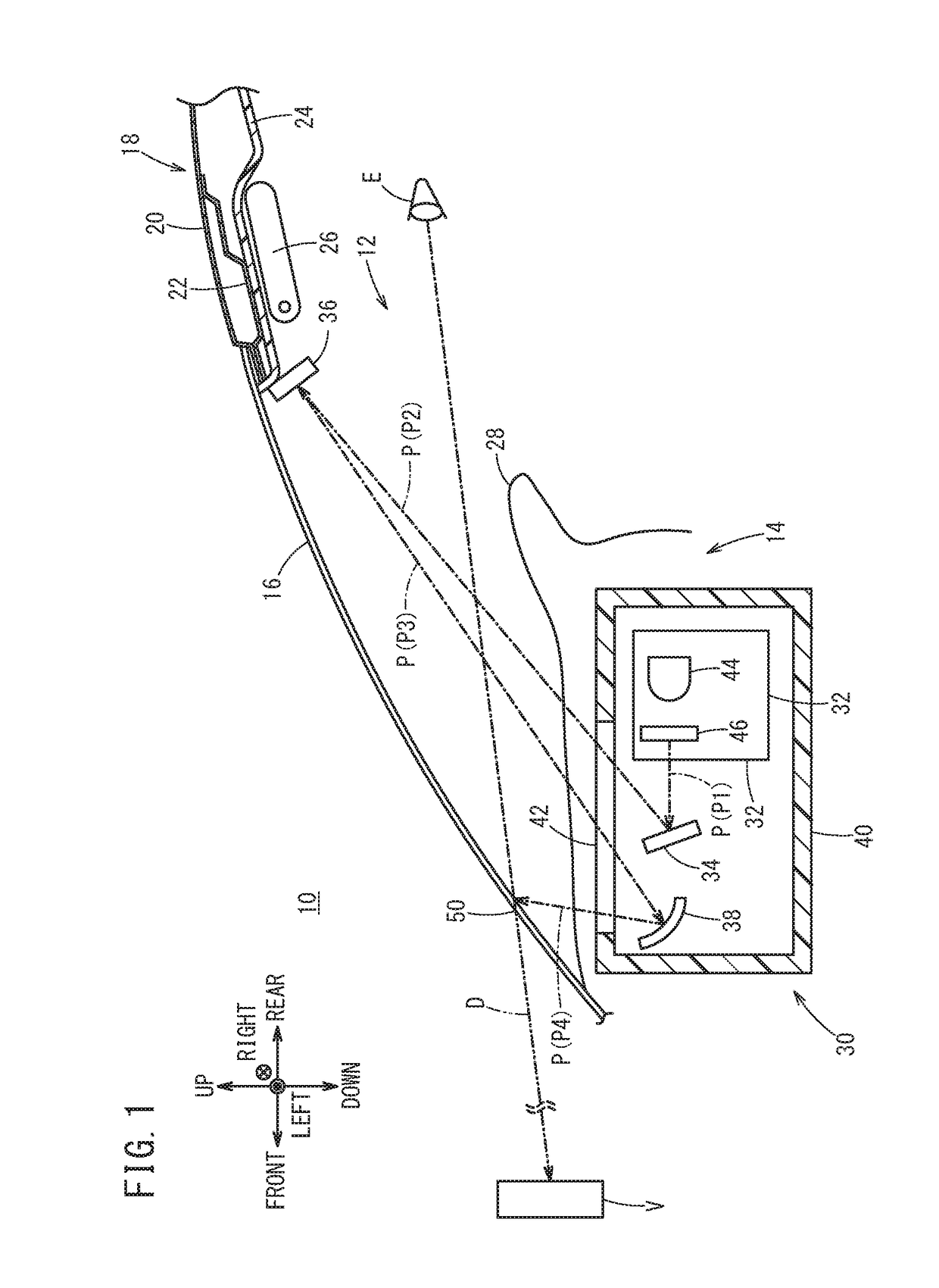
[0028]As illustrated in FIG. 1, a windshield 16 is provided between a front part of a vehicle room 12 and the outside of the vehicle 10. An upper end part of the windshield 16 is connected to a roof 18. The roof 18 includes a roof panel 20 and a front roof rail 22 whose front ends are coupled to each other, and an interior member 24 positioned on the vehicle room 12 side of the roof 18. A front part of the interior member 24 is provided with a sun visor 26. On the other hand, a lower part of the windshield 16 faces a dashboard 28 in the vehicle room 12. In the vehicle room 12, a head-up display device 14 is provided near the windshield 16.

[0029]The head-up display device 14 includes an HUD unit 30 provided inside the dashboard 28, a second reflector 36 disposed at the roof 18 near the windshield 16, and an image formation unit 50 corresponding to a part of the windshield 16.

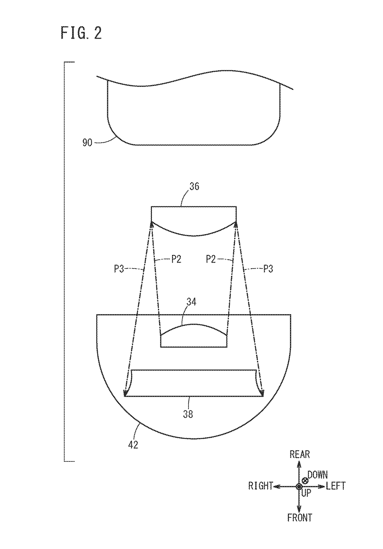
[0030]The HUD unit 30 is disposed in front of a driver's seat 90 (FIG. 2) and includes a projector 32, a first...


PUM


Abstract

In a head-up display device, projection light P emitted from a projector is reflected by a plurality of reflectors (first reflector, second reflector, third reflector) and then, the projection light P is formed into an image on an image formation unit. Among the projector and the reflectors, the first reflector and the third reflector are housed in a casing. Among the reflectors, the second reflector is disposed at a roof near a windshield of a vehicle.

Description

CROSS-REFERENCE TO RELATED APPLICATION[0001]This application is based upon and claims the benefit of priority from Japanese Patent Application No. 2017-062042 filed on Mar. 28, 2017, the contents of which are incorporated herein by reference.BACKGROUND OF THE INVENTIONField of the Invention[0002]The present invention relates to a head-up display device that projects an image to an image formation unit of a vehicle.Description of the Related Art[0003]Japanese Laid-Open Patent Publication No. 2008-296635 discloses a head-up display device (hereinafter also referred to as HUD) that achieves size reduction and forms an image (virtual image) at a far position by extending an optical path length. In this device, projection light emitted from a displayer is reflected by a combiner, the projection light reflected by the combiner is reflected by a first reflector, the projection light reflected by the first reflector is reflected by a second reflector, the projection light reflected by the s...

Claims


Application Information

Patent Timeline
Patent Type & Authority Applications(United States)
IPC IPC(8): G02B27/01B60K37/02B60K35/00
CPCG02B27/0101B60K37/02B60K35/00B60K2350/2052G02B2027/015B60K35/23B60K2360/23B60K2360/334B60K35/60B60K2360/771
Inventor ICHINOKAWA, JUMPEI
Owner HONDA MOTOR CO LTD
Learn More