Machining status display apparatus, and NC program generating apparatus and NC program editing apparatus provided with the same

a status display and status technology, applied in the direction of electrical programme control, program control, instruments, etc., can solve the problems of increasing power consumption, machining accuracy, and high cost, and achieves cost reduction, efficient machining of workpieces, and increased machining accuracy.

Active Publication Date: 2019-08-20
DMG MORI CO LTD
View PDF6 Cites 0 Cited by
  • Summary
  • Abstract
  • Description
  • Claims
  • Application Information

AI Technical Summary

Benefits of technology

[0006]In the field of machining using an NC machine tool, efficient machining of a workpiece and cost reductions are of continued interest. At the same time, the demand for increased machining accuracy continues as technology advances. Therefore, in machining a workpiece with an NC machine tool, it is necessary to comprehensively consider machining efficiency, machining costs, and machining accuracy to set machining conditions (cutting conditions) which provide preferable machining efficiency, machining costs, and machining accuracy.
[0007]The manners in which machining efficiency, machining costs, and machining accuracy are pursued, however, are often in tension, and operators often do not have sufficient knowledge about them. For example, in the case of using a milling cutter, improvement of machining efficiency, that is, shortening of a machining time can be achieved by increasing a width of cut and a depth of cut of the milling cutter and increasing a tool rotation speed and a tool feed rate. However, such an approach increases power consumption and shortens a tool life, which will be factors of increase of machining costs. Further, increase of the width of cut and the depth of cut and increase of the feed rate will be factors of deterioration of machining accuracy.

Problems solved by technology

The manners in which machining efficiency, machining costs, and machining accuracy are pursued, however, are often in tension, and operators often do not have sufficient knowledge about them.
However, such an approach increases power consumption and shortens a tool life, which will be factors of increase of machining costs.
Further, increase of the width of cut and the depth of cut and increase of the feed rate will be factors of deterioration of machining accuracy.
Thus, machining-related evaluation items which are associated with machining efficiency, machining costs, and machining accuracy (for example, a machining time, a machining accuracy, and a tool life) are in tension with each other, and their mutual relationship is quite complicated.
Therefore, operators who have no skilled knowledge do not have accurate knowledge about their mutual relationship.
Therefore, when correcting automatically determined standard cutting conditions in the above-described conventional automatic cutting condition setting apparatus, an ordinary operator cannot determine what correction coefficients should be used for the correction to obtain preferable cutting conditions which are based on comprehensive consideration of machining efficiency, machining costs, and machining accuracy.
As a matter of fact, such an automatic cutting condition setting apparatus cannot set preferable cutting conditions based on the above-described comprehensive consideration.

Method used


Image

  • Machining status display apparatus, and NC program generating apparatus and NC program editing apparatus provided with the same
  • Machining status display apparatus, and NC program generating apparatus and NC program editing apparatus provided with the same
  • Machining status display apparatus, and NC program generating apparatus and NC program editing apparatus provided with the same

Examples


Embodiment Construction

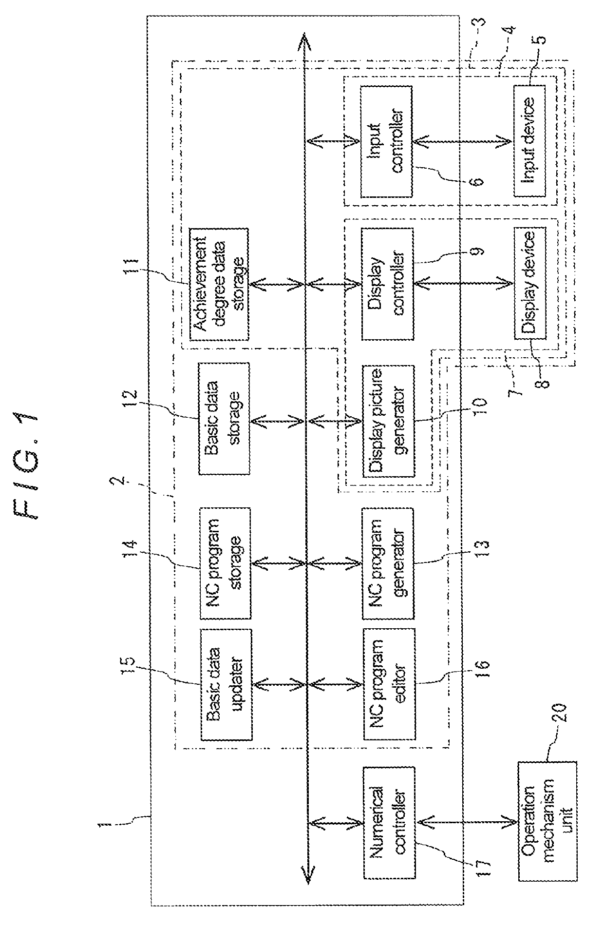
[0056]Hereinafter, a specific embodiment of the present disclosure will be described with reference to the drawings. FIG. 1 is a block diagram showing a schematic configuration of an NC program generating and editing apparatus according to the embodiment.

[0057]As shown in FIG. 1, the NC program generating and editing apparatus 2 according to this embodiment includes a machining status display apparatus 3, a basic data storage 12, an NC program generator 13, an NC program storage 14, an NC program editor 16, and a basic data updater 15. Further, the machining status display apparatus 3 includes an achievement degree data storage11, a display picture generator 10, an input controller 6, a display controller 9, an input device 5, and a display device 8. Each of the above-mentioned components is described in detail below.

[0058]Note that the input controller 6, the display controller 9, the display picture generator 10, the achievement degree data storage 11, the basic data storage 12, t...


PUM


Abstract

A machining status display apparatus includes an achievement degree data storage storing achievement degree data relating to a degree of achievement of each of predetermined machining-related evaluation items within a range determined by attainable maximum and minimum values of the evaluation item and storing the degrees of achievement of the evaluation items obtained under each of predetermined sets of machining conditions in association with the set of machining conditions, a display part displaying the degrees of achievement of the evaluation items corresponding to a selected set of machining conditions by referring to the data in the achievement degree data storage, and an input part inputting a selection signal for selecting a set of machining conditions. The display part displays the degrees of achievement of the evaluation items obtained under the set of machining conditions corresponding to the selection signal by referring to the data in the achievement degree data storage.

Description

BACKGROUNDField of the Disclosure[0001]The present disclosure relates to a display apparatus for displaying a machining status which is feasible in a machine tool, and an NC program generating apparatus and an NC program editing apparatus each provided with the display apparatus.Background of the Disclosure[0002]In the field of machining using an NC machine tool, there has been known an NC program generating apparatus that automatically generates an NC program. Such an NC program generating apparatus sets suitable cutting conditions, such as a spindle rotation speed and a tool feed rate, for each machining step in accordance with a machining step, a workpiece material, a tool material, a machining accuracy, and other factors.[0003]A known example of such an apparatus capable of automatically setting cutting conditions is an automatic cutting condition setting apparatus disclosed in Japanese Unexamined Patent Application Publication No. H06-079581. This automatic cutting condition se...

Claims


Application Information

Patent Timeline
Patent Type & Authority Patents(United States)
IPC IPC(8): G05B19/404G05B19/4093
CPCG05B19/404G05B19/40937G05B2219/36289G05B19/19G06Q10/0639G05B2219/31399G05B19/4155G05B19/409
Inventor KUMAGAI, NORIHIRONISHIKAWA, SHIZUOIIYAMA, KOJINAKAO, HIROKI
Owner DMG MORI CO LTD
Why Eureka
Try Eureka