Device for capping a container neck

a container and neck technology, applied in the field of capping devices, can solve the problems of current capping, soiled exterior face of the container neck, and cannot provide a satisfactory solution, and achieve the effect of limiting the risk of biological contamination

Active Publication Date: 2016-03-08
TETRA LAVAL HLDG & FINANCE SA
View PDF18 Cites 0 Cited by
  • Summary
  • Abstract
  • Description
  • Claims
  • Application Information

AI Technical Summary

Benefits of technology

[0008]The object of the present invention is to propose a capping device of the type referred to above that makes

Problems solved by technology

This being so, current capping devices, including that proposed by EP-A-1 254 848, do not provide a satisfactory solution for situations where, when filling the container, the exterior face of the neck thereof is soiled by the product with which the container is filled.
Indeed, in the event of overfilling, product

Method used


Image

  • Device for capping a container neck
  • Device for capping a container neck
  • Device for capping a container neck

Examples


Embodiment Construction

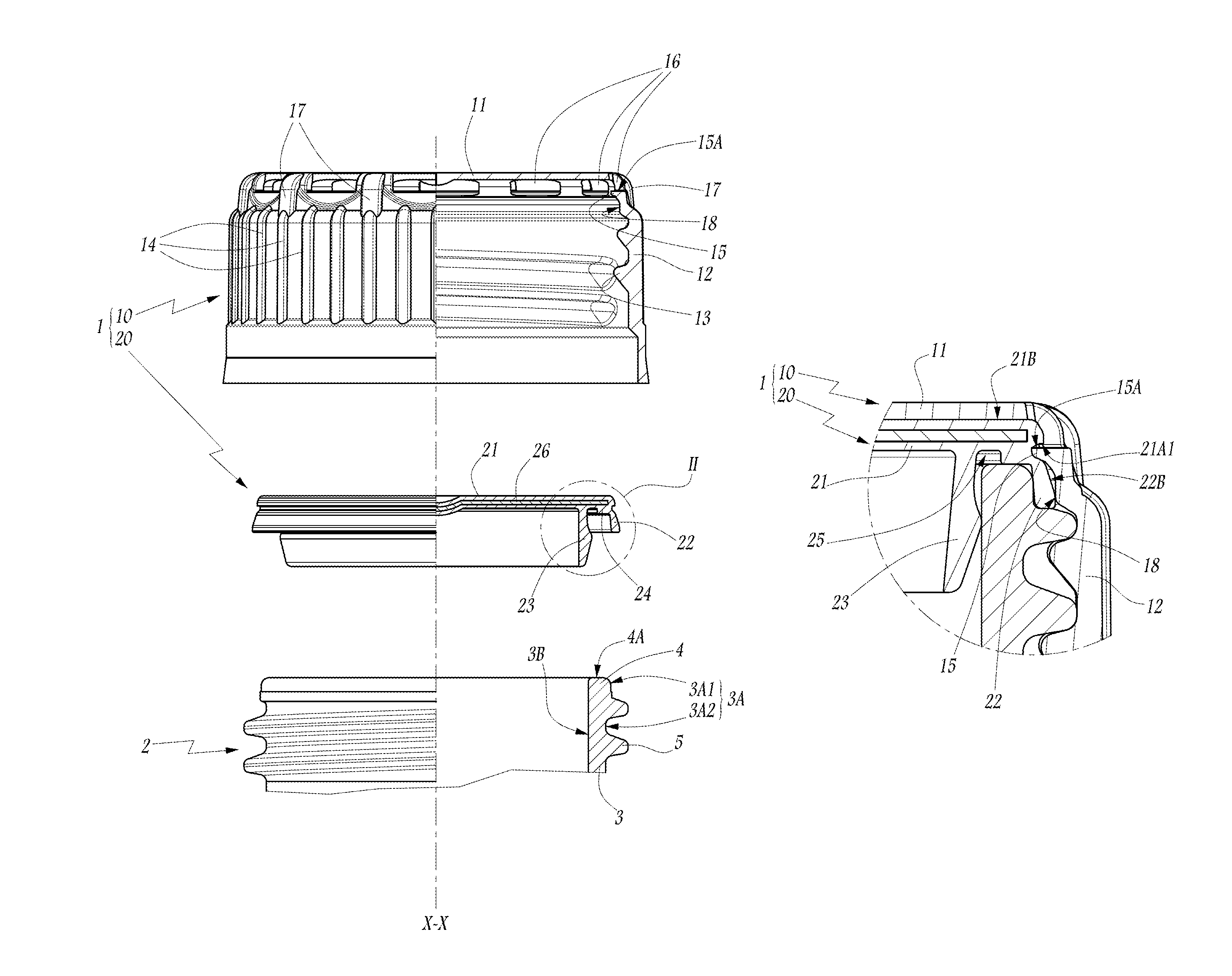
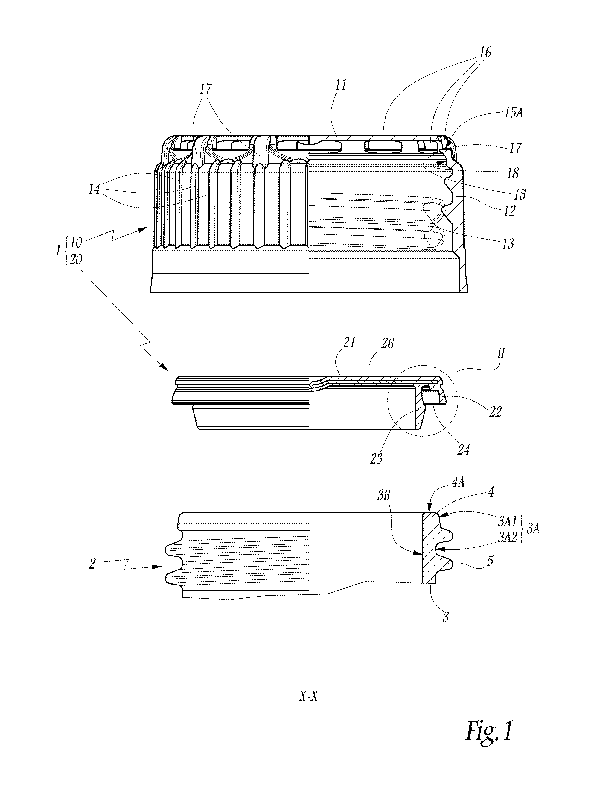
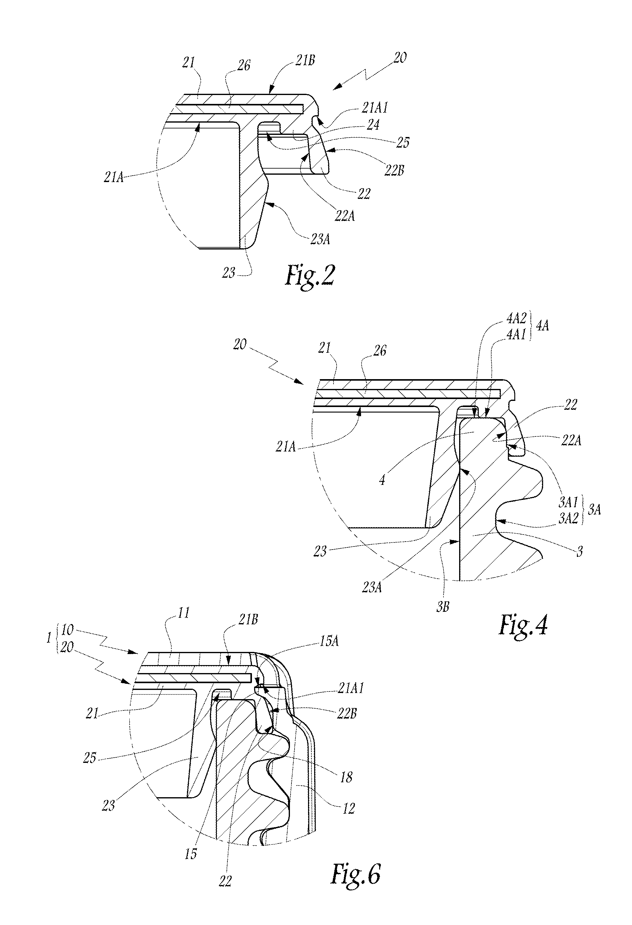
[0022]In FIGS. 1 to 6 there is represented a device 1 for capping a neck 2 of a container.

[0023]In practice, the neck 2 is either made in one piece with the rest of the container, notably when the latter is a glass or plastic material bottle, or adapted to be permanently fastened to a wall of the container, in an opening passing through that wall.

[0024]The neck 2 has a globally tubular shape, with a central longitudinal axis X-X. For convenience, the remainder of the description is oriented taking the terms “upper” and “top” as corresponding to a direction globally parallel to the axis X-X and extending from the body of the container toward the free end of its neck 2, i.e. an upward direction in the figures, while the terms “lower” and “bottom” correspond to an opposite direction.

[0025]The neck 2 includes a globally cylindrical body 3 with a circular base and axis X-X. At its top end 4, this body 3 delimits an edge 4A at the level of which the product contained in the container is i...


PUM


Abstract

A capping device includes an external outer cap adapted to be removably fixed to the exterior face of a container neck, and an internal insert adapted to plug the opening of the neck. The insert is adapted to be fitted to the neck independently of the outer cap and before fitting the outer cap to the neck. When it is fitted to the neck, the outer cap is adapted to be permanently fastened to the insert. When filling the container, the insert may include means for retaining it on the neck adapted to connect the insert mechanically to the neck before the outer cap is fitted to the neck, thereby sealing at least the exterior peripheral surface of the free end of the neck against a cleaning liquid applied externally to the neck.

Description

CROSS-REFERENCE TO RELATED APPLICATIONS[0001]This is a U.S. National Phase of PCT / EP2012 / 053993, filed Mar. 8, 2012, which claims the benefit of priority to French Patent Application No. 11 51920, filed Sep. 3, 2011, which is incorporated herein by reference.TECHNICAL FIELD[0002]The present invention concerns a device for capping a container neck.[0003]The invention relates generally to caps comprising two main components, namely an external outer cap, which is designed to be fixed removably around the neck of a container, notably by screwing-unscrewing, and an internal insert, which is designed to block the neck in sealed manner and which, during assembly of the cap, is permanently fastened inside the outer cap.BACKGROUND[0004]In a field that the invention does not concern capping devices of this type are known in which the insert is first added to and permanently fixed inside the outer cap, before thereafter placing on a container neck to be capped the combination consisting of th...

Claims


Application Information

Patent Timeline
IPC IPC(8): B65D41/58B65D41/04B67B6/00B65D41/00B65D41/34
CPCB65D41/005B65D41/04B65D41/58B67B6/00
Inventor WOOD, CHRISTOPHERLUZZATO, MICHELBERNARD, VERONIQUEANTIER, GREGORY
Owner TETRA LAVAL HLDG & FINANCE SA
Why Eureka
Try Eureka