
Method and apparatus for preventing stack overflow in embedded system

a stack overflow and embedded system technology, applied in the field of embedded systems, can solve the problems of stack overflow, limited memory resources in the entire system, and limited stack regions

Active Publication Date: 2016-03-08
SAMSUNG ELECTRONICS CO LTD
View PDF10 Cites 0 Cited by
  • Summary
  • Abstract
  • Description
  • Claims
  • Application Information

AI Technical Summary

Benefits of technology

This patent discusses a method and apparatus for preventing a stack overflow in an embedded system without adding extra processing time. The apparatus includes a calculator that calculates the maximum amount of memory a main function of a thread image may use, and a storage module that stores this information. The dynamic loading module then selectively loads the thread image based on its current memory capacity and the calculated maximum usage of memory. This helps to ensure efficient use of memory and prevents buffer overflows, which can improve the performance and reliability of embedded systems.

Problems solved by technology

The embedded system has strict restrictions in terms of cost, size, power consumption, and the like, such that it is not preferable that resources be allocated for a future request that cannot be predicted.
Hence, a memory resource in the entire system is limited, so that a stack region is also limited.
Therefore, when a particular task uses all of the stack allocated to the task and tries to access memory that is outside the region reserved for the stack to store information on the task, a problem occurs, that is, a stack overflow occurs.
The static analysis technique that is used to prevent stack overflow does not execute the program, however, analyzes the program itself.
However, this technique cannot be applied to a system in which the components of the system are dynamically changed.
The run-time check technique that is used to prevent stack overflow does not predict the amount of stack used, however, allocates a predetermined stack and checks whether the stack overflow occurs during run-time.
Moreover, since whether the stack overflow occurs is continuously checked during run-time, a run-time overhead may occur.

Method used


Image

  • Method and apparatus for preventing stack overflow in embedded system
  • Method and apparatus for preventing stack overflow in embedded system
  • Method and apparatus for preventing stack overflow in embedded system

Examples


Embodiment Construction

[0029]Reference will now be made in detail to the embodiments, examples of which are illustrated in the accompanying drawings, wherein like reference numerals refer to the like elements throughout. The embodiments are described below to explain the present invention by referring to the figures.

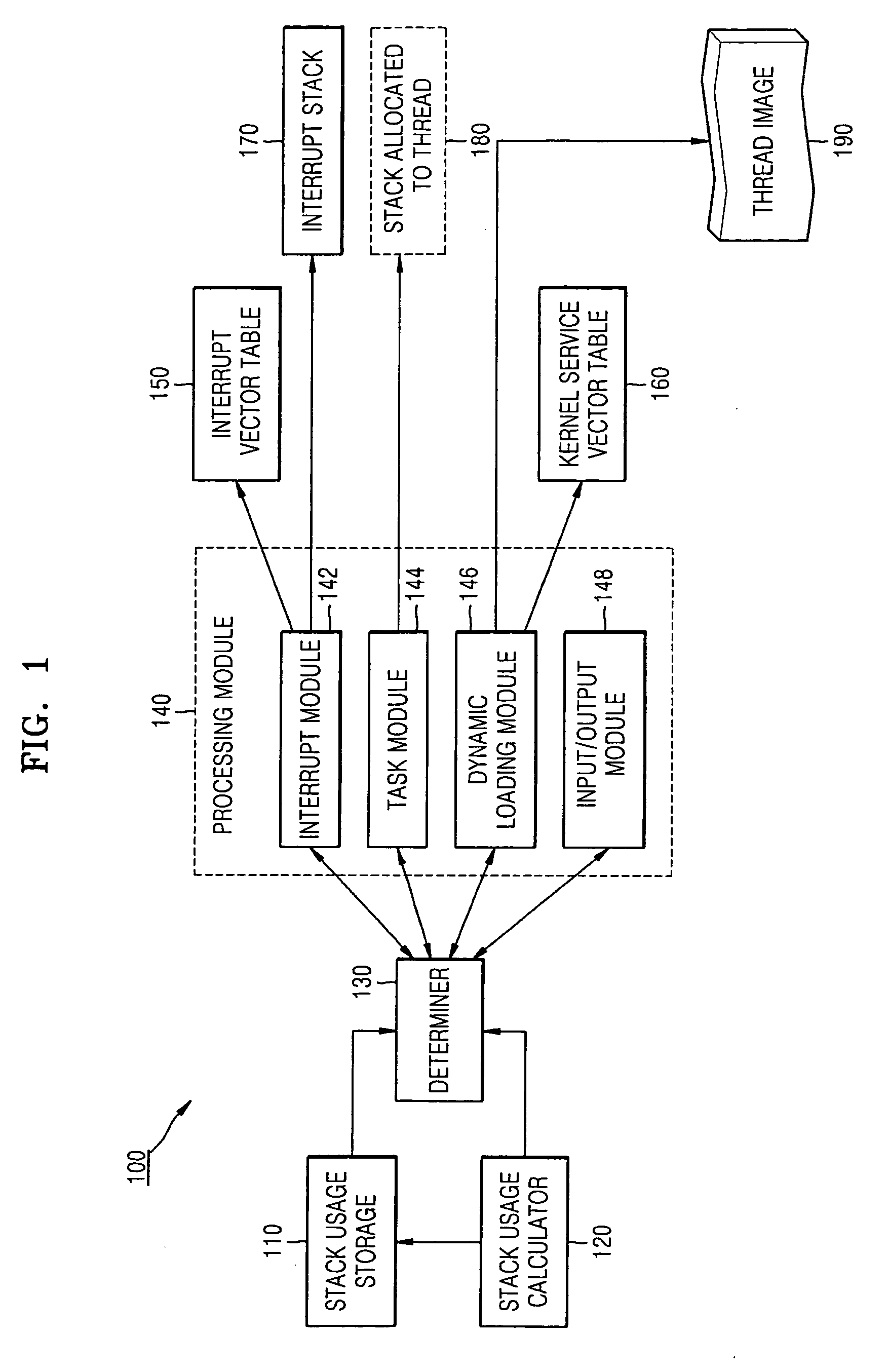
[0030]FIG. 1 is a block diagram of an apparatus 100 for preventing a stack overflow of an embedded system, according to an embodiment. Referring to FIG. 1, the apparatus 100 for preventing a stack overflow includes a stack usage storage 110, a stack usage calculator 120, a determiner 130, a processing module 140, an interrupt vector table 150, and a kernel service vector table 160. The stack usage storage 110, the stack usage calculator 120, the determiner 130, and the processing module 140 may be included in a kernel of the embedded system.

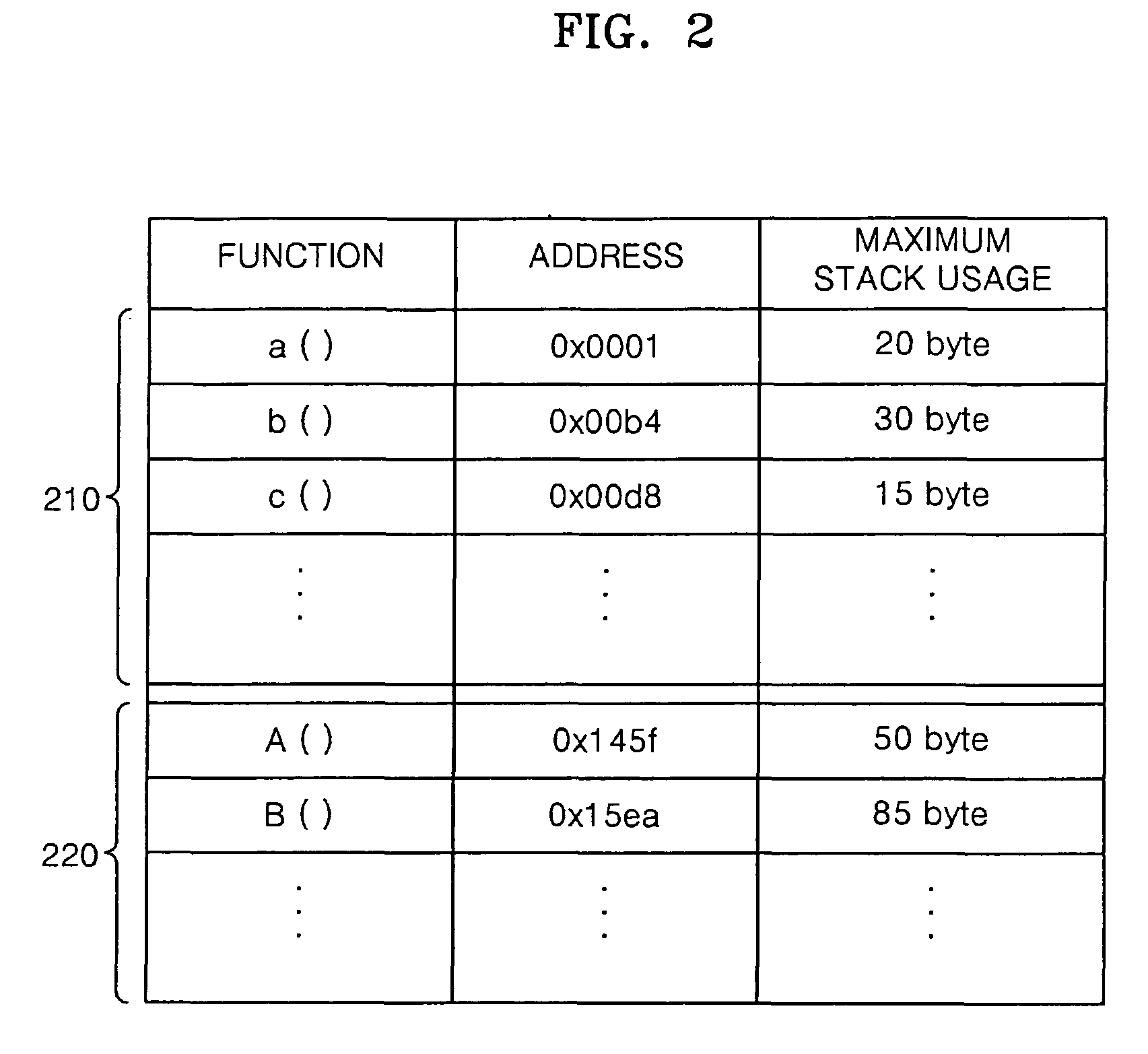
[0031]The stack usage storage 110 stores addresses of functions provided from the kernel, a maximum stack usage used by each of the functions, an address o...


PUM


Abstract

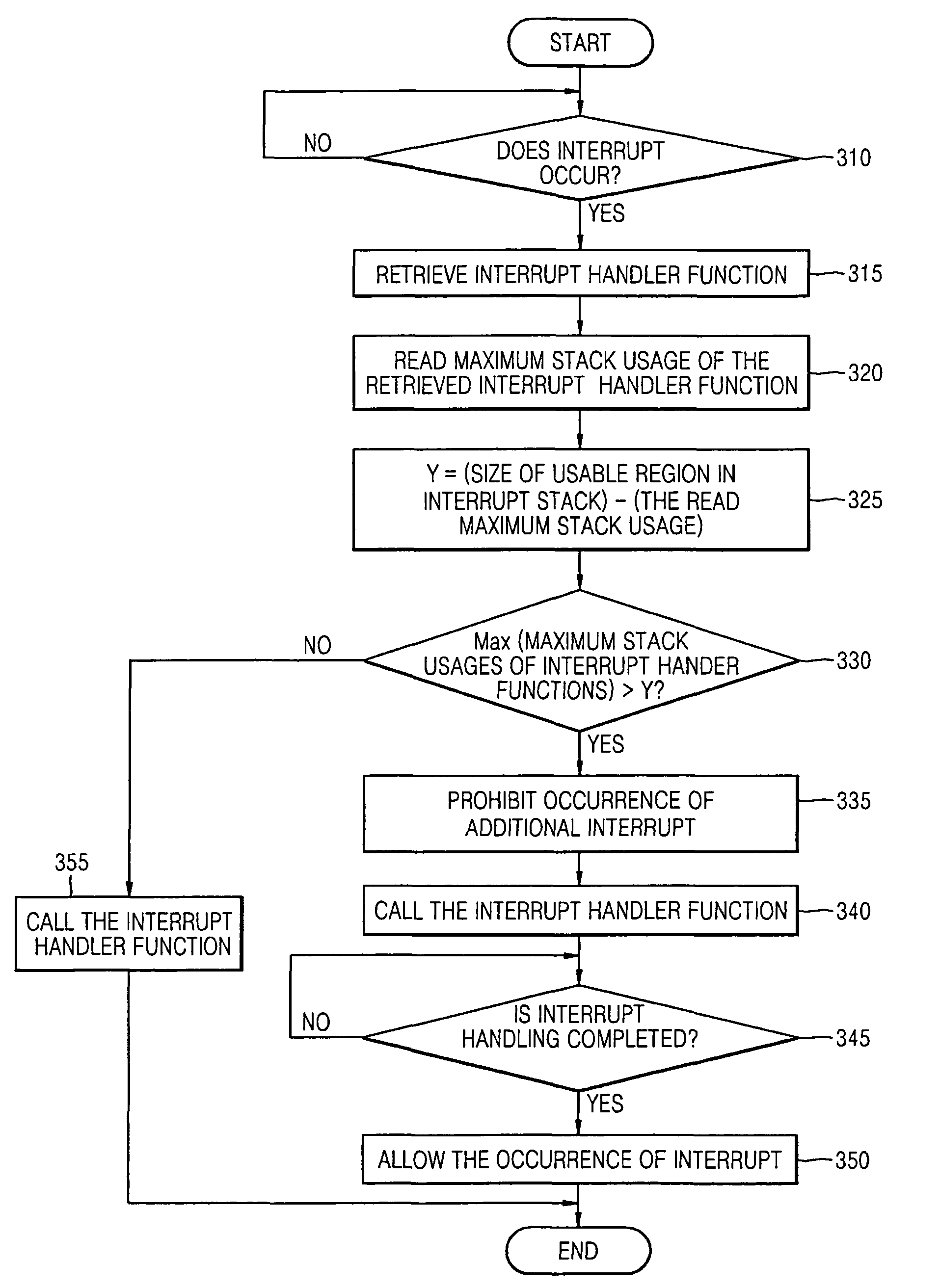
Provided is a method and apparatus for preventing a stack overflow in an embedded system. The method of preventing a stack overflow includes: reading a maximum stack usage of at least one function for executing a requested operation from maximum stack usages of functions provided from a kernel, which are stored in advance; and processing the requested operation on the basis of the read maximum stack usage of the at least one function and a size of a usable region in a stack for the requested operation. Accordingly, the stack overflow can be prevented without generating a run-time overhead.

Description

CROSS-REFERENCE TO RELATED APPLICATIONS[0001]This application claims the benefit of Korean Patent Application No. 10-2007-0001643, filed on Jan. 5, 2007, in the Korean Intellectual Property Office, the disclosure of which is incorporated herein in its entirety by reference.BACKGROUND[0002]1. Field[0003]One or more embodiments relate to an embedded system, and more particularly, to a method and apparatus for preventing a stack overflow in an embedded system.[0004]2. Description of the Related Art[0005]An embedded system is a system in which a microprocessor or a microcontroller is embedded and designed to perform a dedicated function. The embedded system is also conventionally referred to as a particular application system that is a part of a large system, and includes hardware or software for performing a dedicated function. The embedded system is applied to various kinds of fields such as a control field including factory automation, home automation, robot control, and process cont...

Claims


Application Information

Patent Timeline
Patent Type & Authority Patents(United States)
IPC IPC(8): G06F13/24G06F9/50
CPCG06F13/24G06F9/5016G06F2209/504Y02B60/142Y02D10/00G06F9/06G06F12/00G06F12/06
Inventor LEE, SEUNG-WONKIM, HAN-CHEOLSHIN, YOUNG-SAMJEONG, MIN-KYUYIM, KEUN-SOOYOO, JEONG-JOONLEE, JAE-DON
Owner SAMSUNG ELECTRONICS CO LTD
Learn More