AI technical title is built by Patsnap AI team. It summarizes the technical point description of the patent document.
a script logic and logic technology, applied in the field of script logic, can solve the problems of requiring much time and effort to debug, and the design of panel logic and branching logic can be extremely complex, so as to save time, facilitate the use, and reduce the difficulty of time-consuming
Active Publication Date: 2016-03-15
ALORICA
View PDF13 Cites 0 Cited by
Summary
Abstract
Description
Claims
Application Information
AI Technical Summary
This helps you quickly interpret patents by identifying the three key elements:
Problems solved by technology
Method used
Benefits of technology
Benefits of technology
[0010]All panels that are associated with the script but are not reachable through any of the current paths are listed in a missing panels list-box. This is a key item as often times these panels are left out of the script design unintentionally. For large scripts, this allows a developer to quickly glance at the panels not currently being used and identify if a mistake may have been made.
[0011]A list of all paths and panels that are part of the script's current routing are also displayed for filtering purposes. If the script path value is changed, the listed panels are filtered to only display panels that are part of the specified path. This is a quick reference for the developer to determine which panels are currently being used in a specific path. Each filtered view can be selected for display allowing the user to quickly visually track progress down specific script paths at any level to ensure the proper script flow is taking place. The script routing and logic can be visually understood and checked by individuals, for example non-technical individuals, with no training in the scripting tool itself. The present invention allows non-development management and end-client review of scripts. From a development stand point, the ability to review the script visually from an optional scale is key in logic tracking, testing and trouble shooting of scripts.
[0012]The display can either show all routes out of a path / panel or into a script path or panel. In the case of a display of all routes into a path or panel, routing lists are searched for the target path or panel. All routes where the target is found are shortened so the target is the end point and the graph is rendered. This view allows an agent to quickly display all routes in a script into a specific panel which is often important for testing and trouble shooting and can be a very difficult and time consuming task if performed manually.
[0013]When the displayed image is accessed, for example by “clicking” the image, the position is determined. If a box was found to be clicked on the left side, a quick redraw from that path or panel takes place. This feature is provided in order to save time and make the interface more user friendly. If the box is clicked on the right side, the panel is “drilled into” and the user is routed to a drill down page. The panel's HTML page is displayed in the right frame for visual confirmation. The panel's code related to the file is then read and split into the primary function sections representing the life cycle of a panel, such as load, edit, submit, and branch. This information is made available on the left frame. Any possible navigations points out of the current panel are also listed as links allowing for script navigation from the drill down page. If the navigation takes place, the drill down page is reloaded for the new panel. The drill down page allows script developers to quickly view a panel and its code from the visual display and when a closer look is needed, one click will display the page itself and its related code. This allows developers to quickly check for code or display errors. The script can then be navigated from this view to allow for a visual “walk through” of the different script routes. The present invention allows technical or non-technically trained personal to quickly and easily see the displayed screens without any script logic specific training
Problems solved by technology
The design of panel logic and branching logic can be extremely complex due and requires much time and effort to debug.
Method used
Image
Click on the blue label to locate the original text in one second.
Reading with bidirectional positioning of images and text.
Examples
Embodiment Construction
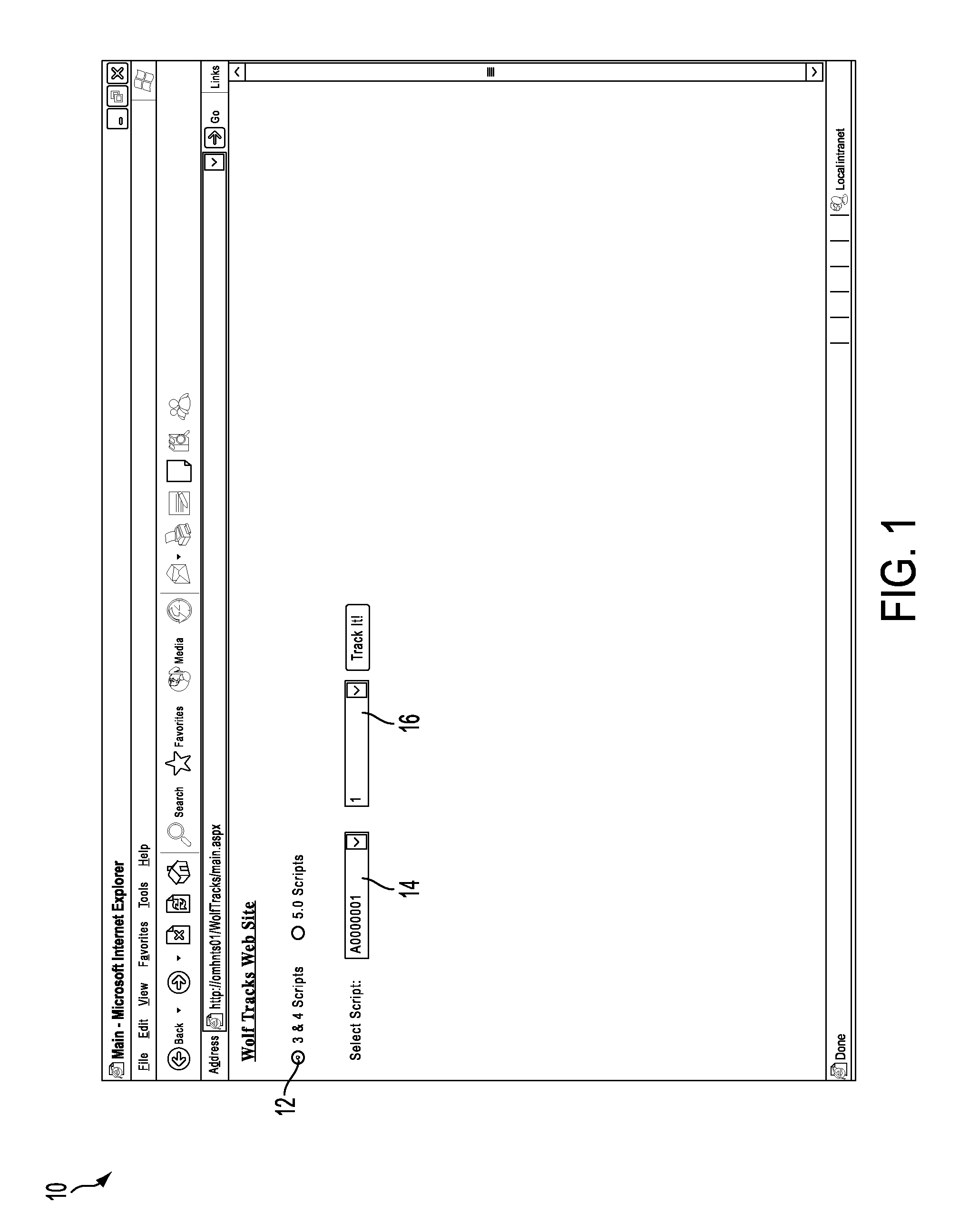
[0042]Referring now to FIG. 1, a main screen 10 providing the script logic graphical mapping of the present invention is depicted and comprises a number of blocks or modules that may be software, hardware, firmware, and / or the combination of software, hardware, and / or firmware. The main screen allows a version of a script 12, a script logic name 14 and a panel within the script 16 to be selected by the user.
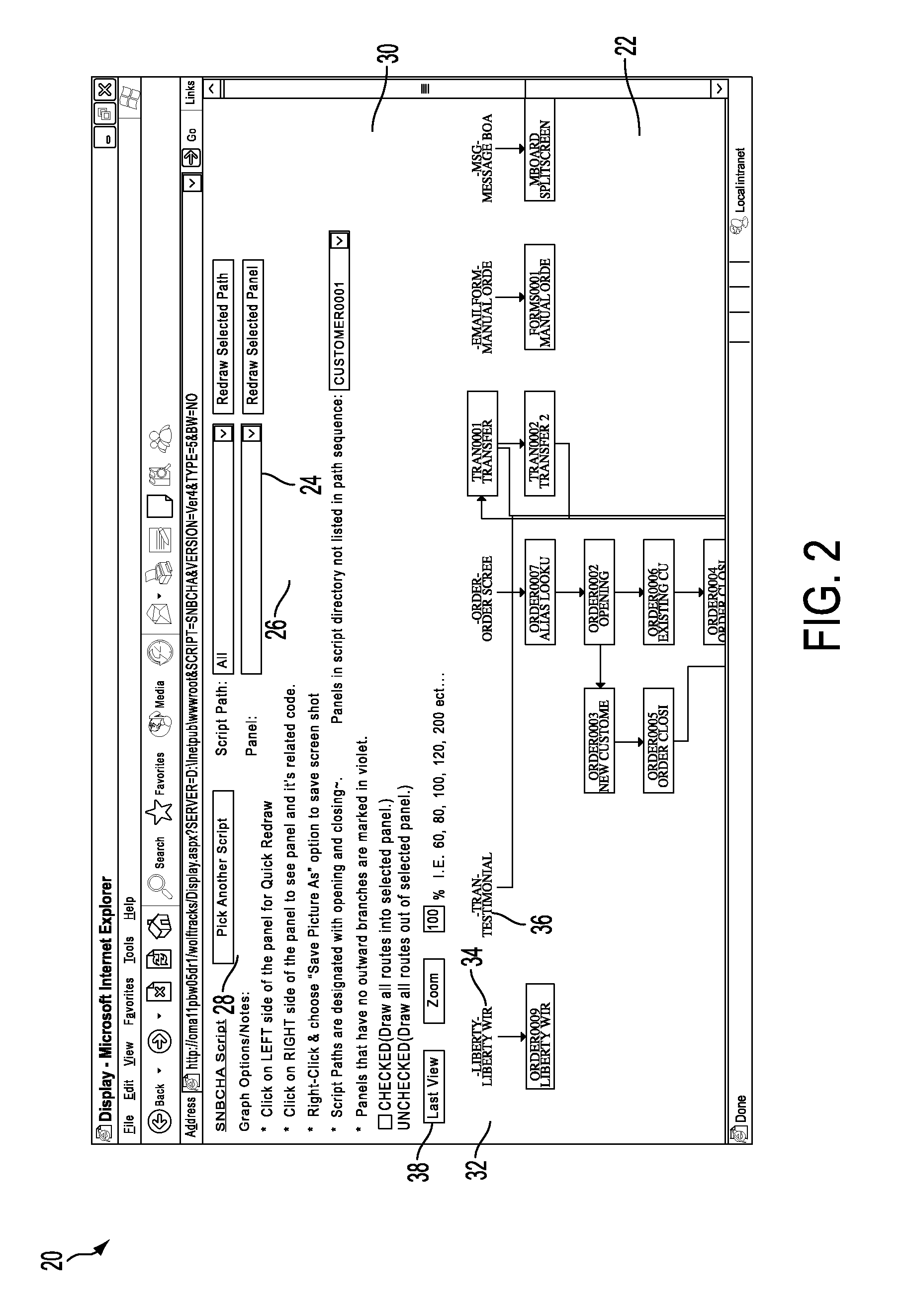
[0043]Referring now to FIG. 2, a display screen 20 providing the script logic graphical mapping of the present invention is depicted and comprises a number of blocks or modules that may be software, hardware, firmware, and / or the combination of software, hardware, and / or firmware. The display screen 20 shows a graphical representation of the script logic 22. The user selectable criteria include a selected logic script path 24, a specified panel within the script path 26 and the ability to restart and choose another script logic 28. The display also indicates panels that are in th...
PUM
Abstract
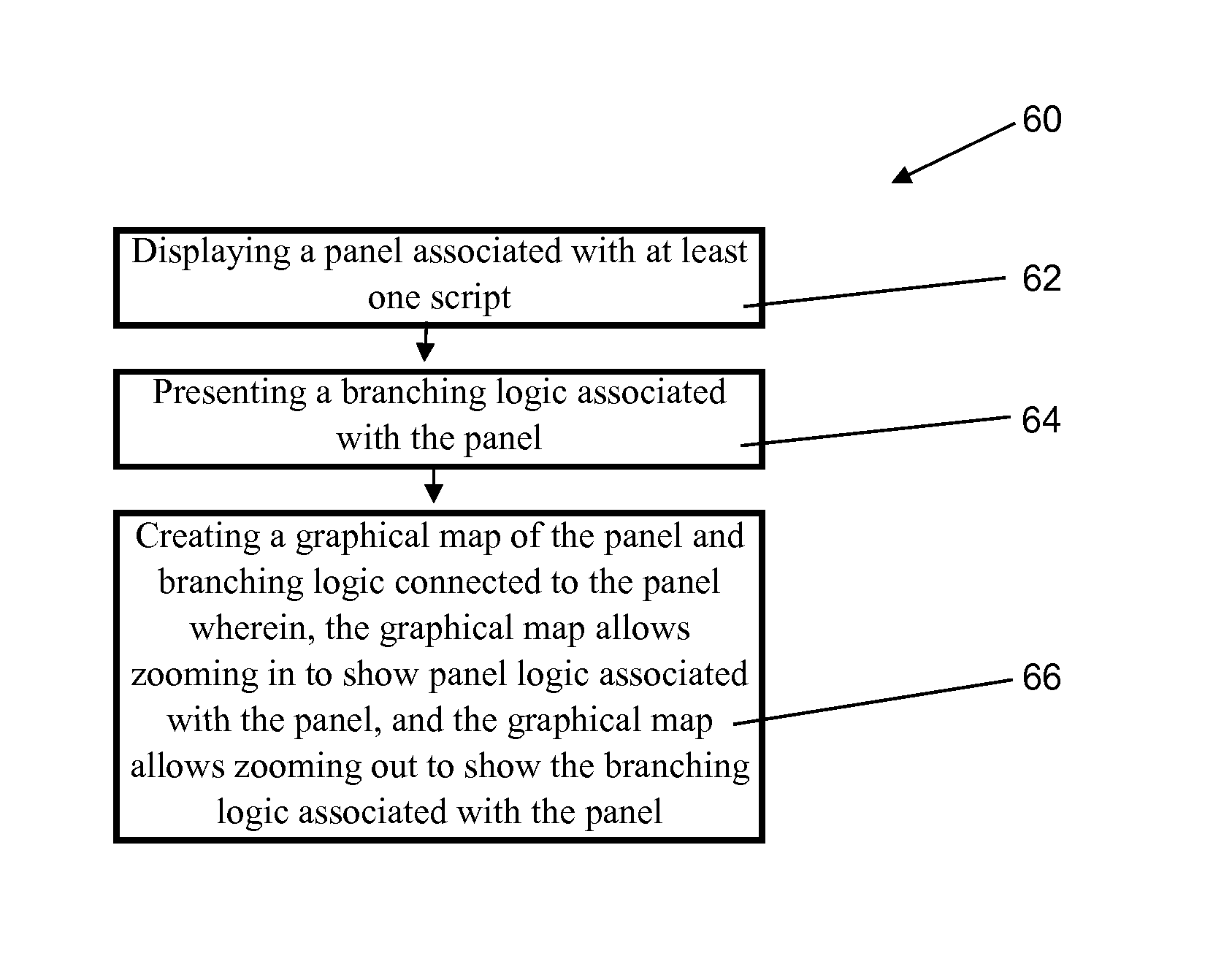
A system, method, and computer readable medium comprises displaying a panel associated with at least one script, presenting a branching logic associated with the panel and creating a graphical map of the panel and the branching logic where the graphical map allows zooming in to show panel logic associated with the panel, and the graphical map allows zooming out to show the branching logic associated with the panel.
Description
CROSS REFERENCE TO RELATED APPLICATIONS[0001]The present patent application is a continuation from U.S. patent application Ser. No. 11 / 427,009, entitled SCRIPT LOGIC GRAPHICAL MAPPING, filed on Jun. 28, 2006 which is related to U.S. patent application Ser. No. 11 / 427,013 entitled REMOTELY MONITORING CALL CENTER STATISTICS, filed Jun. 28, 2006, and U.S. patent application Ser. No. 11 / 427,010 entitled SESSION INITIATION PROTOCOL ENABLED AGENT DESKTOP ENVIRONMENT, filed Jun. 28, 2006, and U.S. patent application Ser. No. 11 / 427,008 entitled SCRIPT LOGIC VIEWING, filed Jun. 28, 2006, and U.S. patent application Ser. No. 11 / 427,007 entitled REAL TIME FEEDBACK OF SCRIPT LOGIC, filed on Jun. 28, 2006, and U.S. patent application Ser. No. 11 / 427,014 entitled CONTACT CENTER CALL ROUTING BY AGENT ATTRIBUTE filed on Jun. 28, 2006, the entire contents of which are incorporated by reference herein.BACKGROUND OF THE INVENTION[0002]The present invention is generally related to script logic, and mo...
Claims
Application Information
Patent Timeline
Application Date:The date an application was filed.
Publication Date:The date a patent or application was officially published.
First Publication Date:The earliest publication date of a patent with the same application number.
Issue Date:Publication date of the patent grant document.
PCT Entry Date:The Entry date of PCT National Phase.
Estimated Expiry Date:The statutory expiry date of a patent right according to the Patent Law, and it is the longest term of protection that the patent right can achieve without the termination of the patent right due to other reasons(Term extension factor has been taken into account ).
Invalid Date:Actual expiry date is based on effective date or publication date of legal transaction data of invalid patent.

