
Connector with force multiplying mechanism

a technology of force multipliing mechanism and connector, which is applied in the direction of connection, electrical apparatus, coupling device connection, etc., can solve the problem that the force multipliing effect of a single lever may not be sufficient, and achieve the effect of enhancing the press-contact force and

Active Publication Date: 2016-03-15
SUMITOMO ELECTRIC WIRING SYST INC
View PDF5 Cites 6 Cited by
  • Summary
  • Abstract
  • Description
  • Claims
  • Application Information

AI Technical Summary

Benefits of technology

The solution allows for a more compact and efficient connection of multiple poles by eliminating interference between adjacent connectors and enabling miniaturization of the lever, while maintaining effective force multiplication and sealing capabilities.

Problems solved by technology

A force multiplying effect of a single lever may not be sufficient if the connector has a large number of poles.

Method used


Image

  • Connector with force multiplying mechanism
  • Connector with force multiplying mechanism
  • Connector with force multiplying mechanism

Examples


Embodiment Construction

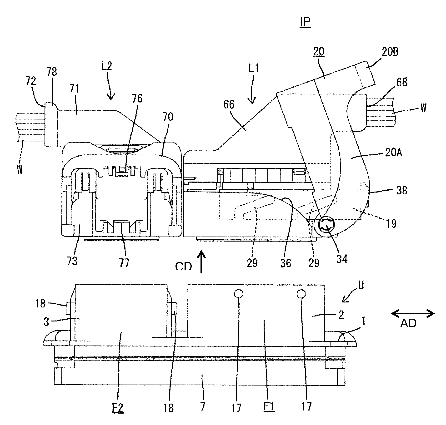
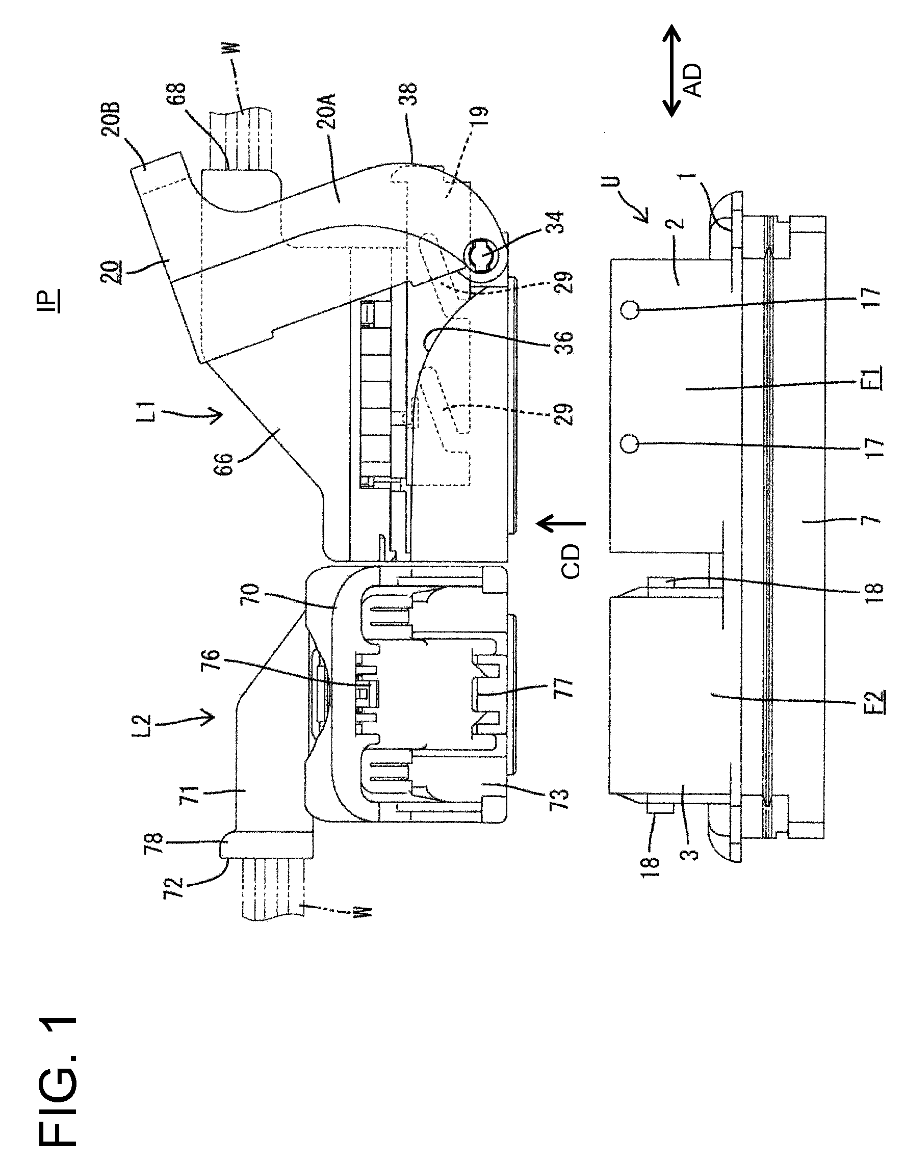
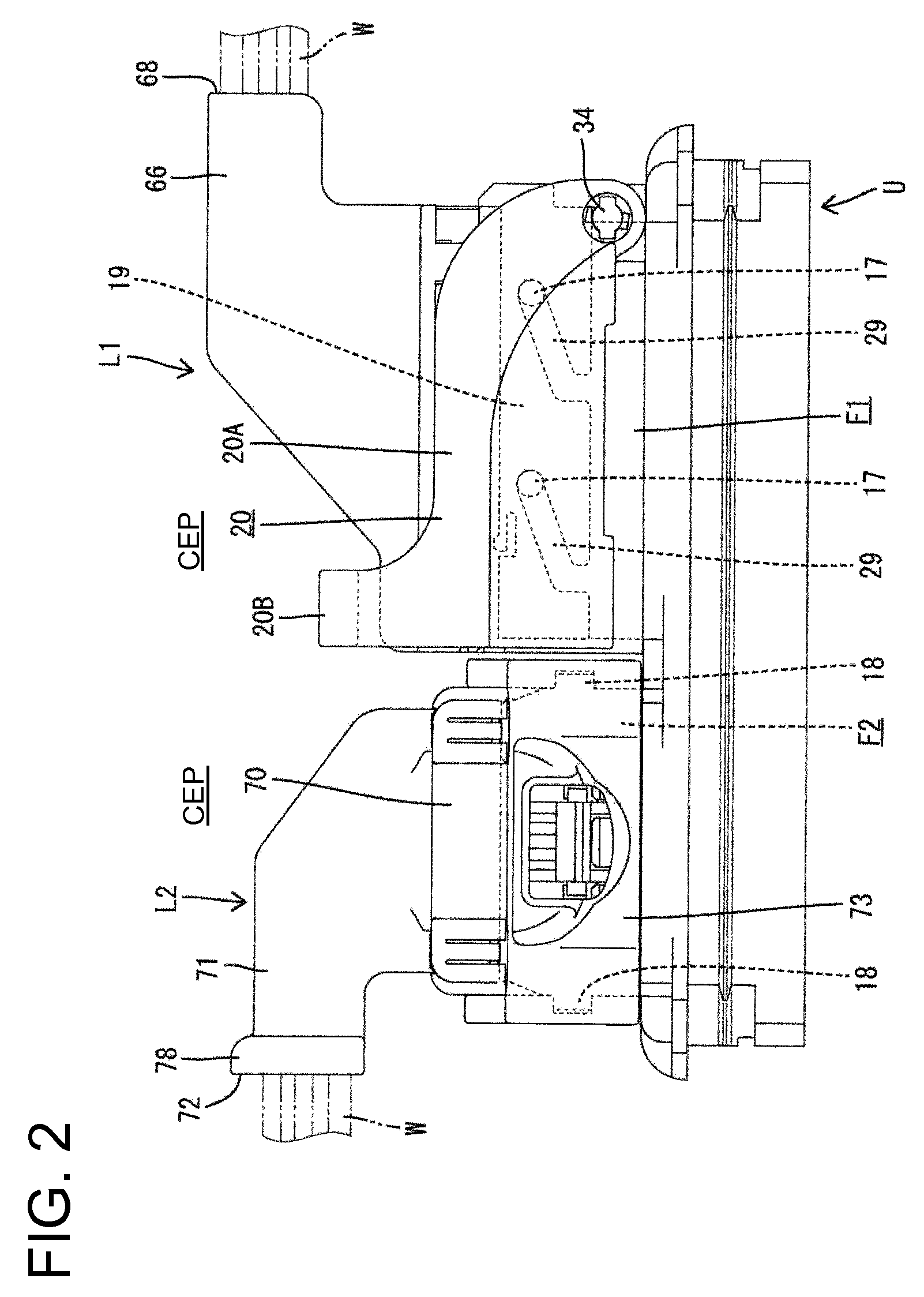
[0059]FIGS. 36(A) and 36(B) show adjacent fixed connectors 100, 101. FIG. 36B shows the prior art arrangement where surfaces with cam followers 102, 103 are parallel, while FIG. 36A conceptually shows the invention where surfaces with the cam followers are perpendicular. In either case, rotating directions of levers on mating connectors are parallel to the surfaces with the cam followers 102, 103. Areas enclosed by imaginary lines in FIGS. 36(A) and 36(B) schematically show rotation ranges of the levers. Force multiplying actions of a lever can be made stronger by lengthening the lever so that the lever projects more from the connector. Tips of the levers that projecting from the prior art connectors of FIG. 36B face each other and may interfere with each other. Therefore, an interval D1 between the prior art fixed-side connectors has to be widened. However, the subject invention avoids interference of the levers and narrows the interval between the fixed-side connectors to D2, wher...


PUM


Abstract

A connector with a force multiplying mechanism includes first and second fixed connectors (F1, F2) which are arranged side by side and each of which includes cam followers (17, 18), and first and second lever connectors (L1, L2) which are individually connectable to the respective fixed connectors (F1, F2) and each of which includes a rotatably provided lever (20, 70) and is connectable to the corresponding one of the fixed connectors (F1, F2) by a force multiplying action produced by rotating the lever (20, 70) while the cam followers (17, 18) and the lever (20, 70) are engaged directly or indirectly via a slider (19). The first and second fixed connectors (F1, F2) are so arranged that surfaces where the cam followers (17, 18) are formed are perpendicular to each other.

Description

BACKGROUND[0001]1. Field of the Invention[0002]The invention relates to a connector with a force multiplying mechanism.[0003]2. Description of the Related Art[0004]A lever-type connector utilizes a lever that can be rotated to multiply forces for connecting connectors. A force multiplying effect of a single lever may not be sufficient if the connector has a large number of poles. As a countermeasure, Japanese Unexamined Patent Publication No. 2011-216441 considers dividing each connector into a plurality of parts, arranging the divided parts adjacent to each other and providing another force multiplying mechanism. More particularly, two male connectors with cam followers are arranged adjacent to each other on the same wall and levers are provided separately on two female connectors to be connected to the male connectors. The male connectors should be arranged at a narrow interval. However, the surfaces of the male connectors that have the cam followers face the same direction. Thus,...

Claims


Application Information

Patent Timeline
Patent Type & Authority Patents(United States)
IPC IPC(8): H01R13/629H01R27/02
CPCH01R13/62922H01R27/02H01R13/62977
Inventor SUZUKI
Owner SUMITOMO ELECTRIC WIRING SYST INC
Learn More