
Press

a press and guiding unit technology, applied in the field of presses, can solve the problems of defective pressing results, deformation of press components, and considerable additional expense of tool guiding units, and achieve the effect of high motor weigh

Active Publication Date: 2016-03-22
MASCHFAB LAUFFER
View PDF10 Cites 2 Cited by
  • Summary
  • Abstract
  • Description
  • Claims
  • Application Information

AI Technical Summary

Benefits of technology

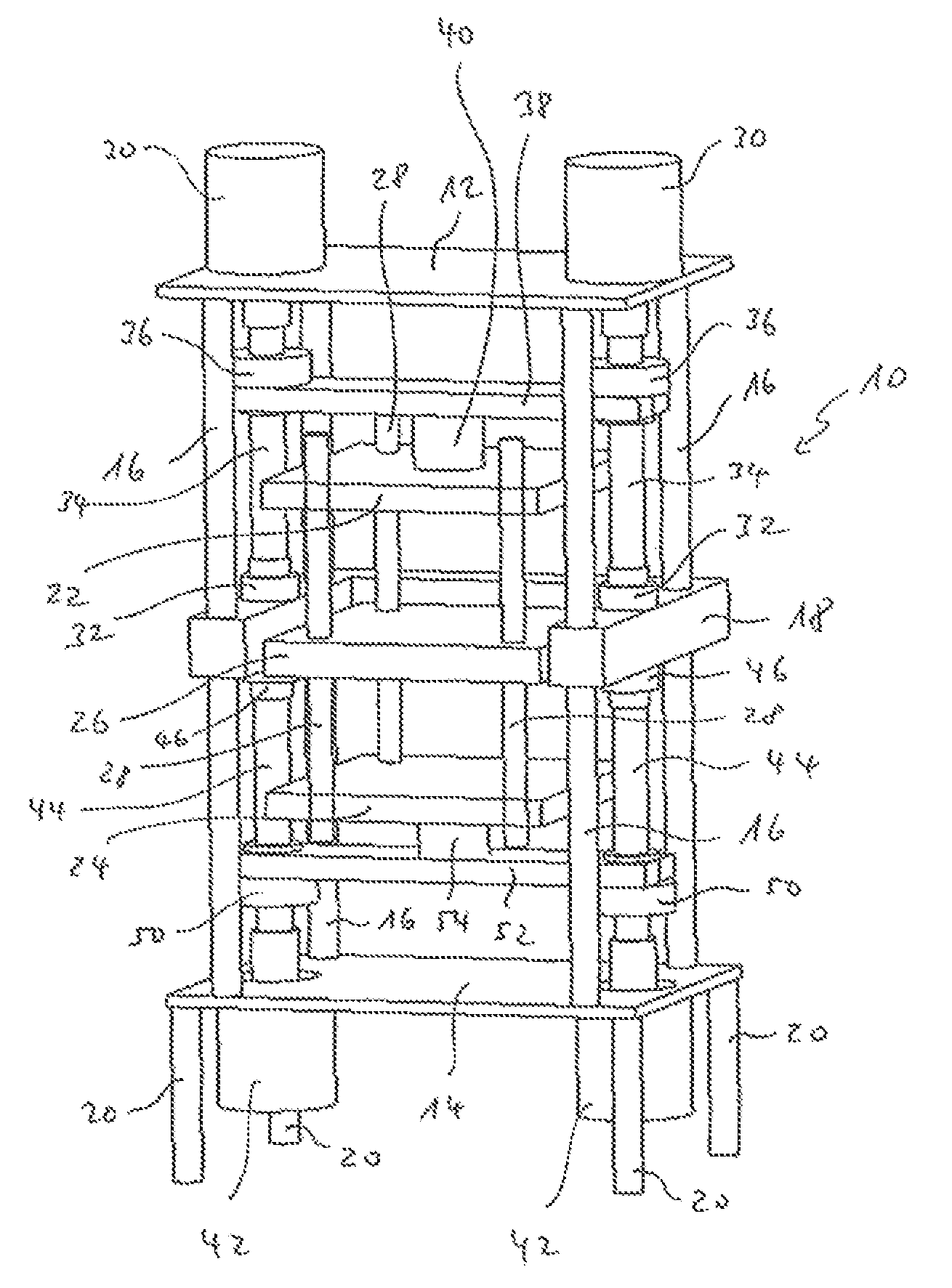
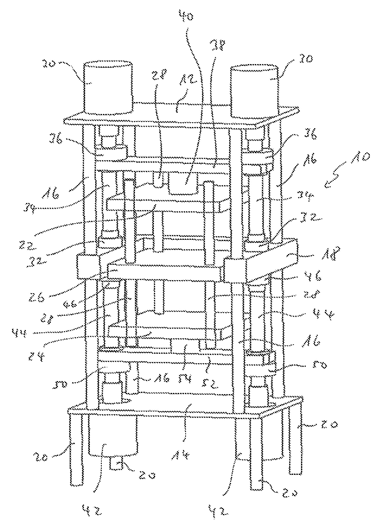
[0008]The die assembly may have a die plate. Likewise, the upper and / or the lower punch unit or units may have an upper or a lower punch plate. An aligning unit for the tool guiding unit may be provided, with which the latter may be aligned relative to the supporting element while being inserted in the press frame. Upper and / or lower drive units are provided for moving the upper and / or lower punches vertically in the course of the pressing. Basically, is possible to provide more than one, for example two, upper drive units and more than one, for example two, lower drive units. If two upper drive units and / or two lower drive units are provided, these may be disposed, for example, symmetrically on two mutually opposite sides of the press frame. It is, however, also conceivable to provide a drive unit only on one side and to have a guide unit on the opposite side. As explained, the lower drive unit can drive a lower punch unit or a die assembly in the vertical direction. The press can therefore be operated by the ejection method, for which the die assembly is stationary, and the upper and lower punches are moved relative to the die assembly as well as by the withdrawal method, for which the lower punch is stationary and the die assembly as well as the upper punch are moved. Basically, the number of press axes and, with that, the pellets produced in parallel can be increased within wide limits.
[0009]The press frame of the inventive press has a supporting element, which is disposed between the retaining plates. The supporting element may be disposed, for example, essentially in the middle between the retaining plates. The supporting element is formed separately from the die assembly or a die plate of the die assembly and can absorb large forces. According to the invention, the tool guiding unit is disposed at the supporting element. In addition, in accordance with the invention, the upper drive unit and / or the lower drive unit, when the press is in operation, are supported at the supporting element, in particular directly and, moreover, in such a manner, that the reaction forces, which are generated as action forces by the pressing forces produced during the pressing of the powdered material in the at least one mold holder, are passed at least predominately into the supporting element. In the course of a pressing procedure, the upper and lower punches exert a considerable pressing force, produced by the upper and / or lower drive unit, on the powdered material, which is to be pressed into a pellet. This pressing force, as an action force, produces a reaction force or counter force, which, in turn, acts over the upper and lower punches on the upper and / or lower drive unit. In accordance with the invention, this reaction force, which is introduced by the upper and lower punches into the upper and / or lower drive unit, is thus passed into the supporting element. The remaining parts of the press frame, in particular the vertical spacers between the retaining plates, essentially, do not participate in this force flux. These forces are also not passed once again over the upper and / or lower drive unit into the die assembly. In particular, the inventive press frame is a press frame without pillars, for which the vertical spacers do not have to be designed for absorbing high pressing forces. Since the force essentially does not flow over the comparatively long pillars of a press frame, the frame spring of the press is less. Any deformation of the press frame and the therewith associated undesirable effects on the results of the pressing are largely avoided. Moreover, advantageously, only a few components of the press are in the force flux. As a result, only a few component tolerances are cumulative. The components, which are in the flux flow in accordance with the invention, in particular the carrying frame, can be manufactured constructively in a less expensive manner with low tolerances. A precise pressing result can therefore be achieved at a lower cost than with the prior art. Moreover, the total height of the press is low, since the drive units can be integrated in the frame of the press.
[0010]The die assembly and the supporting element of the press frame can be disposed in the same or in a slightly spaced apart location plane. The location plane, in particular, is a horizontal plane. The die assembly, in particular a die plate, as well as the supporting element usually extend in a direction perpendicular to the location plane, in particular in a vertical direction. The location plane can then, for example, be located centrally with respect to the vertical extent of the die assembly, in particular of the die plate or the supporting element. In the case of this configuration, the mounting level of the die assembly, in particular a die plate can be largely identical with the mounting level of the respective drive unit at the supporting element, if a plane, oriented perpendicularly to the axis of rotation of, for example, a spindle nut system of the drive unit, is defined as the mounting plane. By these means, deformations of components of the press, while the latter is in operation, are avoided further. The die assembly, in particular a die plate, may be fastened to the support element, in particular directly. By these means, deformation of the components of the press is decreased further.
[0012]According to a further development, the upper transfer element may comprise an upper transfer bridge and / or the lower transfer element may comprise a lower transfer bridge. It is then furthermore possible that two upper drive units are provided, which are fastened to the upper transfer bridge, and / or that two lower drive units are provided, which are fastened to the lower transfer bridge. By providing two drive units per press axis, the dimensions of the respective drive units can be smaller. The two drive units, which are assigned to one axis of the press, can be operated in opposite directions with the objective that the reaction torques which are generated by the two driving moments of the drives, compensate one another and, accordingly, do not bring about any deformations in the arrangement, which takes up the drives. An effect, which is compensatory in this respect, is achieved if the threaded spindles of the oppositely operated drives have opposite lead angles (right-handed and left-handed threads). Furthermore, an upper force transfer element may be disposed between the upper transfer bridge and the upper punch unit and / or between the lower transfer bridge and the lower punch unit or the die assembly.
[0013]According to a further development, the upper drive unit may comprise at least one upper spindle drive, which is driven by at least one electric motor. Alternatively, or in addition, the lower drive unit may comprise at least one lower spindle drive, which is driven by at least one electric motor. Particularly high forces can be transferred precisely with spindle drives. At least one electric motor of the upper spindle drive can be fastened to the upper retaining plate of the press frame. Correspondingly, at least one electric motor of the lower spindle drive can be fastened to the lower retaining plate of the press frame. This has the advantage that the motors are not moved during a pressing process and, with that, there are no weight forces. The comparatively high weight of the motors then does not lead to undesirable stresses on the assigned drive units and, with that, on the punch units, these stresses being taken up by the press frame instead. Of course, the motors do not have to be fastened to the retaining plates.
[0017]Basically, it is conceivable that the supporting element is constructed in several parts. For the supporting element, a closed or open profile is possible. For example, the supporting element may have two separate side parts with, in each case, one or more recesses and / or one or more struts. In accordance with a preferred development, the supporting element is formed in one piece. This decreases manufacturing tolerances. According to a further development in this regard, the supporting element may have a U shape, which lies in a plane, which is oriented perpendicularly to the longitudinal axis of the press, and particularly in a horizontal plane. With such a development, the areas of the supporting element, which determine the relevant tolerances of the components, can be produced particularly precisely. In order to increase the stability of the U shape during the operation of the press, the legs of the U-shaped supporting elements can be connected by a detachable strut.

Problems solved by technology

As a result, the manufacturing tolerances add up and, because of the high forces of the press, components of the press may become deformed.
Consequently, the pressing result may be defective.
However, this leads to a considerable additional expense with regard to the tool guiding units.
In addition, during the pressing, there is increased wear of individual components, such as seals and guiding tapes of cylinders in the case of hydraulic presses, spindles and spindle nut units in the case of spindle presses or guides of the tool guiding units.
In addition, for exchanging the press arrangements with their press punches, the press must be largely dismantled, no information being provided about the exchangeability of the holder of the powdered material in the die plate.

Method used


Image

  • Press
  • Press

Examples


Embodiment Construction

[0020]While this invention may be embodied in many different forms, there are described in detail herein a specific preferred embodiment of the invention. This description is an exemplification of the principles of the invention and is not intended to limit the invention to the particular embodiment illustrated.

[0021]An example of the invention is explained in greater detail in the following by means of a drawing. The single FIGURE diagrammatically shows an inventive press in a perspective view. The inventive press has a press frame 10 with an upper retaining plate 12 and a lower retaining plate 14. In the example shown, the upper and the lower retaining plates 12, 14 are connected with one another over four spacers 16, which extend in the vertical direction and with a supporting element 18, which is disposed approximately centrally between the upper and lower retaining plates 12, 14. In the example shown, the supporting element 18 is constructed in one piece and has a U-shaped prof...


PUM

PropertyMeasurementUnit
reaction forcesaaaaaaaaaa
distanceaaaaaaaaaa
force fluxaaaaaaaaaa

Abstract

A press for producing a pellet from powdered material, comprising a press frame with an upper and a lower retaining plate, which are connected to one another by several vertical spacers and with at least one supporting element, which is disposed between the upper and the lower retaining plate, a tool guiding unit with at least one upper punch unit with at least one upper press punch and / or at least one lower punch unit with at least one lower press punch and with a die assembly with at least one holder for powdered material, which is to be pressed by the upper and / or lower press punch, wherein the tool guiding unit is disposed at the supporting element, and at least one upper drive unit for moving the upper punch unit in the vertical direction and / or at least one lower drive unit for moving the lower punch unit and or the die assembly in the vertical direction, wherein, when the press is operating, the upper drive unit and / or the lower drive unit are supported at the supporting element in such a manner, that the reaction forces, which are produced during the pressing of the powdered material in the at least one holder, are generated as action forces, are passed into the supporting element.

Description

CROSS-REFERENCE TO RELATED APPLICATIONS[0001]This application is a U.S. National Stage application which claims priority to PCT / EP2012 / 004304, filed on Oct. 15, 2012, which claims priority to DE 10 2011 116 552.9, filed Oct. 21, 2011, the contents of which are hereby incorporated by reference.BACKGROUND OF THE INVENTION[0002]The invention relates to a press for producing a pellet from a powdered material, for example, a metal or ceramic powder. The powdered material is filled into a mold holder of a die assembly and subsequently pressed into a pellet in the mold holder by an upper punch and a lower punch. One such a press is known, for example, from EP 2 311 587 A1. The known press has a press frame with an upper and a lower part of the press and vertical pillars, which connect the upper and lower parts of the press with one another. As precise an alignment as possible of all components in the force flux during the pressing process is of decisive importance for the result of pressin...

Claims


Application Information

Patent Timeline
Patent Type & Authority Patents(United States)
IPC IPC(8): B22F3/00B30B15/02B30B11/02B30B1/32B30B1/18B29C43/00B30B15/04
CPCB29C43/006B30B1/181B30B1/32B30B11/02B30B15/028B30B15/04B30B15/041
Inventor BEHNS, HOLGERPANNEWITZ, THOMAS
Owner MASCHFAB LAUFFER
Learn More