Lubricant supported electric motor

a technology of electric motors and lubricants, applied in the direction of mechanical equipment, gearing details, magnetic circuit shapes/forms/construction, etc., can solve the problems of difficulty in spindle support, lack of mechanical robustness of on-wheel electric motors, lack of efficiency in converting electric power to mechanical power, etc., to reduce the torsional stiffness of output torque, increase the rotor, and produce additional torque

Inactive Publication Date: 2019-03-28
NEAPCO INTPROP HLDG LLC
View PDF1 Cites 32 Cited by
  • Summary
  • Abstract
  • Description
  • Claims
  • Application Information

AI Technical Summary

Benefits of technology

[0013]The present disclosure includes articles of manufacture, systems, and processes that relate to a lubricant supported electric motor where the rotor of the electric motor is supported on the inside by pressurized lubricant, replacing the rotor axle, and on the outside, between the rotor and stator also by pressurized lubricant. By eliminating the rotor axle and replacing it with pressurized lubricant, the rotors can be increased to produce additional torque when compared to a non-lubricant supported electric motor. The generally incompressible lubricant provides a very rigid support mechanism for the rotor with respect to the stator in place of the rotor axle. As a result, the rotor output shaft may be a lightweight cantilever without the need for additional radial stiffness (such as provided by plain bearings in a non-lubricant supported motor) to absorb shock and vibration as well as reduced torsional stiffness for the output torque of the lubricant supported motor. Additionally, the lubricant provides a low-friction surface for the rotor and stator and provides for temperature regulation using a lubricant circulation system.

Problems solved by technology

However, on-wheel electric motors have a lack of mechanical robustness to survive the harsh on-wheel environment and lack efficiency in converting electric power to mechanical power.
For electric motors in a harsh environment, such as an on-wheel motor subject to significant mechanical shock, the spindle support problem may be challenging due to the very high shock and vibration levels that may be experienced in the wheel end of a vehicle.

Method used


Image

  • Lubricant supported electric motor
  • Lubricant supported electric motor
  • Lubricant supported electric motor

Examples


Embodiment Construction

[0020]Exemplary aspects will now be described more fully with reference to the accompanying drawings. In particular, a number of non-limiting aspects of vehicle driveline components with a wheel support with or without an end gear reduction unit integrated with a wheel end motor is provided so that this disclosure will be thorough and will fully convey the true and intended scope to those who are skilled in the art. It will be apparent to those skilled in the art that specific details need not be employed, that example aspects may be embodied in many different forms and that neither should be construed to limit the scope of the disclosure. It should also be appreciated that the present disclosure can be utilized in connection with other types of vehicle components not described fully herein.

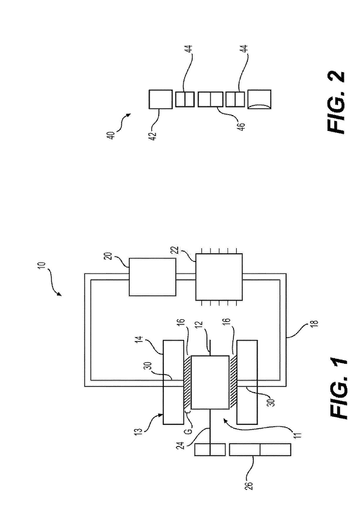
[0021]Referring to FIG. 1, a lubricant supported electric motor 10 is shown having a movable member 11 and a static member 13. The movable member 11 may be configured as a rotor 12 and the static...


PUM


Abstract

A lubricant supported electric motor includes a static member and a movable member movably disposed within the static member to define a gap therebetween. The static member may be configured as a stator and the movable member may be configured as a rotor. The movable member may also be configured to move relative to the static member. The static member and movable member are configured to exert an electromagnetic force therebetween and convert electrical energy into mechanical energy and move the movable member. A lubricant is disposed in the gap between the static member and the movable member to support the movable member relative to the static member.

Description

CROSS-REFERENCE TO RELATED APPLICATIONS[0001]This application claims the benefit of U.S. provisional application No. 62 / 563,735, filed Sep. 27, 2017, which is hereby incorporated by reference as though fully set forth herein.FIELD OF THE DISCLOSURE[0002]The present disclosure relates to electric motors. More particularly, the present disclosure relates to electric motors with lubricant support between a rotor and stator of the electric motor.BACKGROUND OF THE DISCLOSURE[0003]This section of the written disclosure provides background information related to electric motors and is not necessarily prior art to the inventive concepts disclosed and claimed in this application.[0004]Various drivelines in automotive, truck, and certain off-highway applications take power from a central prime mover and distribute the power to the wheels using mechanical devices, such as transmissions, transaxles, propeller shafts, and live axles. These configurations may work well when the prime mover may be...

Claims


Application Information

Patent Timeline
Patent Type & Authority Applications(United States)
IPC IPC(8): F16H57/04H02K9/19H02K7/10H02K7/116H02K1/20H02K5/20
CPCF16H57/0476F16H57/0441F16H57/0413H02K9/19H02K7/1016H02K7/116H02K1/20H02K5/20H02K41/031H02K7/088H02K7/14H02K2201/03H02K5/203F16H57/04
Inventor REMBOSKI, DONALDDEDO, JACQUELINE
Owner NEAPCO INTPROP HLDG LLC
Why Eureka
Try Eureka