Eureka AIR delivers breakthrough ideas for toughest innovation challenges, trusted by R&D personnel around the world.

Pipette with releasable locking of rotational position of actuating element

a technology of rotational position and actuating element, which is applied in the field of pipette, can solve the problems of destroying the locking position, requiring a relatively high force expenditure, and requiring the actuation of the wedge gear system formed by the push button and the lever, and achieves the effect of convenient unlocking, high force, and particularly safe locking

Active Publication Date: 2016-03-29
EPPENDORF SE
View PDF18 Cites 0 Cited by
  • Summary
  • Abstract
  • Description
  • Claims
  • Application Information

AI Technical Summary

Benefits of technology

[0031]In the pipette of the present invention, a set metering volume is secured in that the locking body is arranged on the circumference of the annular cylindrical locking element when it is in the locking position. Through this, the transmission part which the locking element comprises on the outer circumference is held fast. The annular cylindrical locking element can be formed separately from the toothed ring for driving a counter mechanism. Thus, it is possible to perform the locking in arbitrary positions or in more selectable rotational positions than in the conventional locking equipment, where a locking element engages into the toothed ring for driving the counter mechanism. Errors in the setting of the metering volume are reduced through this. Further, finding a locking point is facilitated. The partial cylindrical acting surface of the locking body can be made greater than the one tooth of the locking lever in the state of the art. Thus, the locking can be overcome or destroyed less easily, and the safety of the locking is improved. Further, it is advantageous that the locking body, the unlocking element and the third means for transmitting a movement can be housed in a space-saving way above a toothed ring for driving a counter mechanism. In this, the third means for transmitting do not necessitate a wedge slide gear, which is impaired by friction and increases the force of operation.
[0046]These embodiments of the drive equipment and of the adjustable means for limiting the relocation are constructionally simple and permit to set the metering volume accurately.

Problems solved by technology

The known locking equipment has the disadvantage that it may be destroyed in the locking position by rotating the actuating element with increased force.
Moreover, it is tedious to push the unlocking push button and to adjust the metering volume at the same time.
Moreover, actuating the wedge gear system formed by the push button and the lever requires a relatively high expenditure of force.
Further, the engagement of the tooth into the toothed ring of the transmission part limits the fineness of the setting of the metering volume.
Moreover, the assembly of the many single parts is sumptuous.

Method used


Image

  • Pipette with releasable locking of rotational position of actuating element
  • Pipette with releasable locking of rotational position of actuating element
  • Pipette with releasable locking of rotational position of actuating element

Examples


Embodiment Construction

[0072]While this invention may be embodied in many different forms, there are described in detail herein a specific preferred embodiment of the invention. This description is an exemplification of the principles of the invention and is not intended to limit the invention to the particular embodiment illustrated.

[0073]In the present application, the designations “up” and “down”, “above” and “below” and “horizontal” and “vertical” refer to an orientation of the pipette in which the casing is oriented vertically downward with the seat. In this orientation, a pipette tip fastened on the seat can be directed towards a vessel situated there under, in order to aspirate or to deliver a liquid.

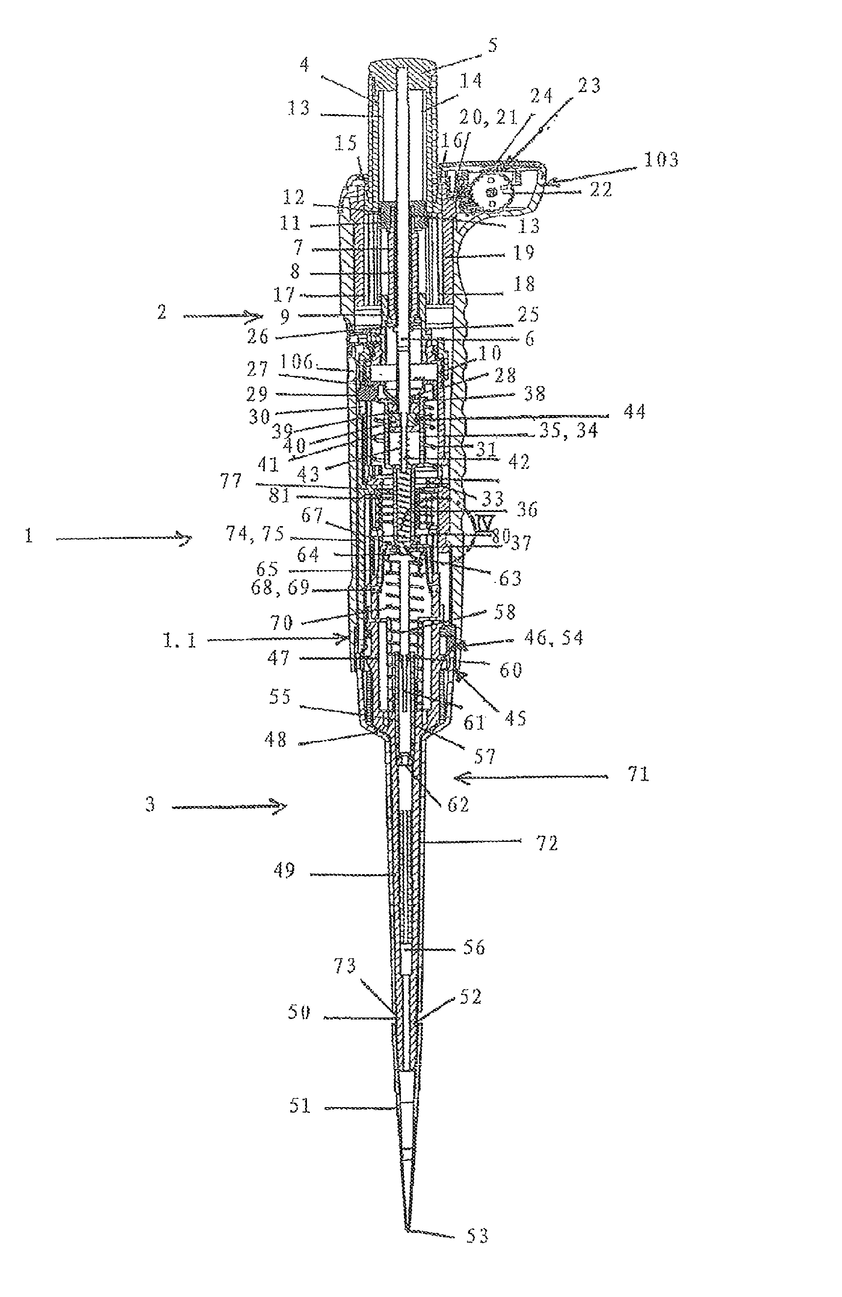
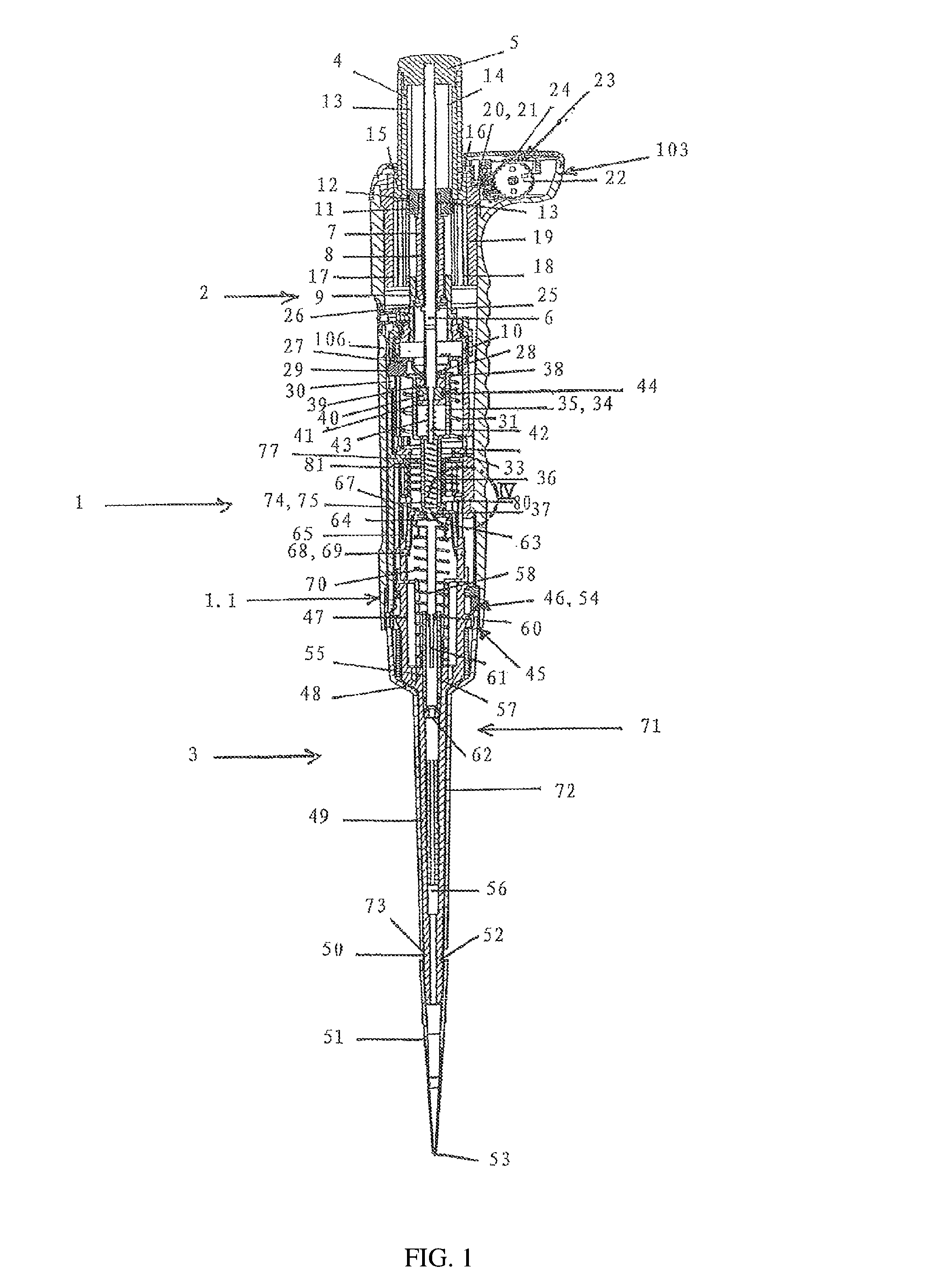
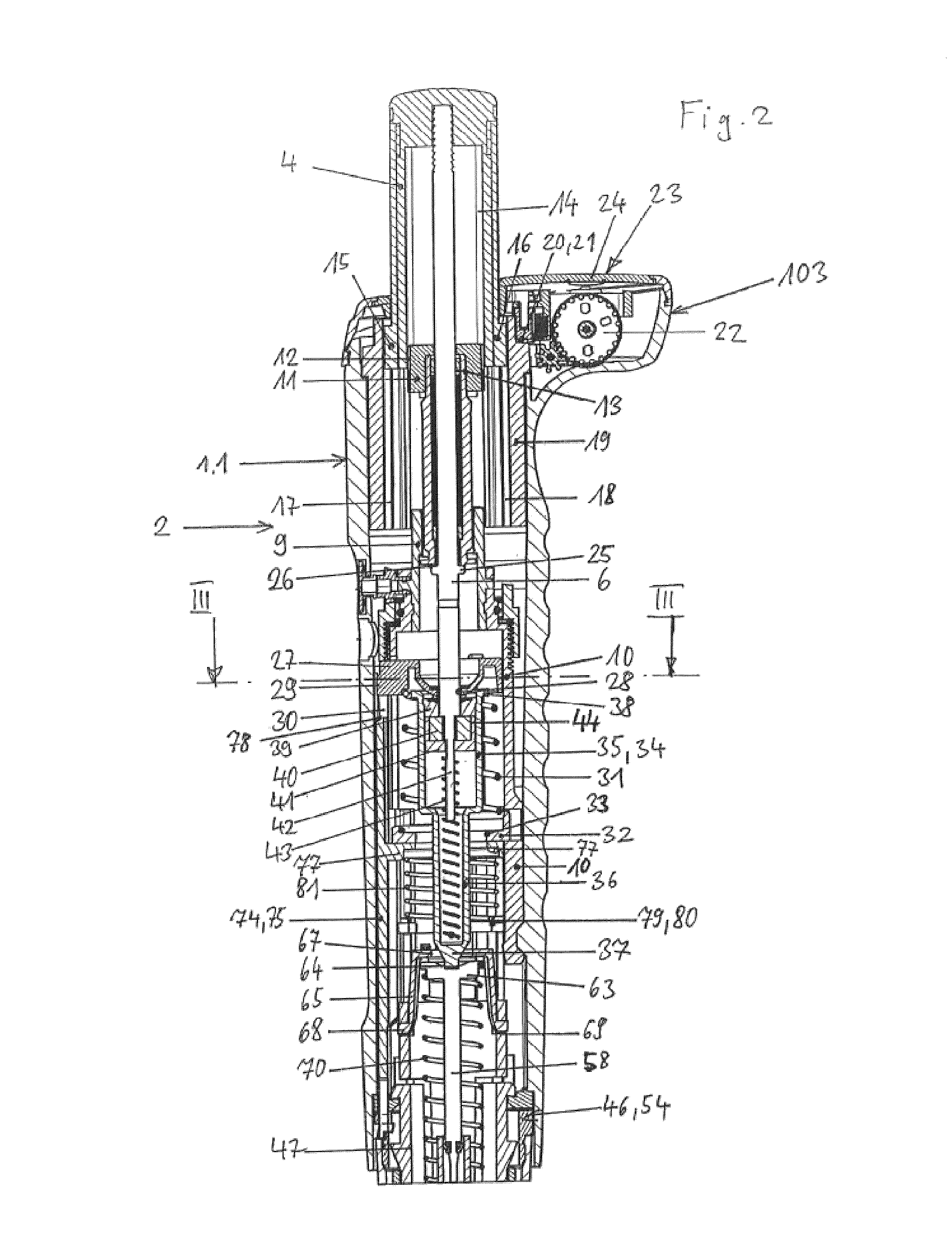
[0074]According to FIGS. 1 and 2, the pipette 1 has a rod-shaped casing 1.1, formed as a handle, with an upper part 2 of the casing and a lower part 3 of the casing. The upper part 2 of the casing forms a drive unit with all the components contained therein, and the lower part 3 of the casing a displac...


PUM


Abstract

A pipette for use with pipette tips in which a set metering volume is secured in that the locking body is arranged on the circumference of the annular cylindrical locking element when it is in the locking position. Through this, the transmission part which the locking element comprises on the outer circumference is held fast. The annular cylindrical locking element can be formed separately from a toothed ring for driving a counter mechanism. Thus, it is possible to perform the locking in arbitrary positions or in more selectable rotational positions than in the conventional locking equipment, where a locking element engages into the toothed ring for driving the counter mechanism.

Description

CROSS-REFERENCE TO RELATED APPLICATIONS[0001]Not applicable.STATEMENT REGARDING FEDERALLY SPONSORED RESEARCH[0002]Not applicable.BACKGROUND OF THE INVENTION[0003]The present invention relates to a pipette for replaceable pipette tips.[0004]Pipettes are used in the laboratory in particular for metering liquids. For this purpose, a pipette tip is clamped fast on a seat of the pipette with an upper opening. The seat is mostly a conical or cylindrical projection with respect to a casing of the pipette, onto which a pipette tip can be clamped with the upper opening thereof. The pipette tip can pick up and give out liquid through a lower opening. Air cushion pipettes comprise a displacement equipment for air, which is communicatingly connected to the pipette tip through a hole in the seat. An air cushion is relocated by means of the displacement equipment, so that liquid is sucked into the pipette tip and ejected out from there. For this purpose, the displacement equipment has a displacem...

Claims


Application Information

Patent Timeline
Patent Type & Authority Patents(United States)
IPC IPC(8): B01L3/02
CPCB01L3/021B01L3/0224B01L2200/14B01L2300/026
Inventor WILMER, JENSWINTER, INGO
Owner EPPENDORF SE
Why Eureka
Eureka Blog
Learn More