Rotor for a rotary press

a rotary press and rotor technology, applied in the direction of presses, shaping presses, manufacturing tools, etc., can solve the problems of not inconsiderable cost, insufficient transmission of lubricant to the upper and lower punches, and the contact between the contact part and the upper or respective lower punches passing through becomes increasingly impaired, so as to achieve constant transmission of lubricant and reduce the degree of wear. , the effect of reducing the degree of wear

Active Publication Date: 2018-05-29
FETTE COMPACTING GMBH
View PDF17 Cites 0 Cited by
  • Summary
  • Abstract
  • Description
  • Claims
  • Application Information

AI Technical Summary

Benefits of technology

[0011]The invention achieves a series of advantages and results in a constant transmission of lubricant to the upper or lower punches by the contact pressure of the contact part remaining the same. This in turn leads to a lower degree of wear of the upper or lower punches by ensuring sufficient lubrication at all times. As a result, it also leads to a lower degree of wear of the control cams and further elements of the rotary press, for example the pressing rollers of the pressing stations.
[0012]Damage to the upper or lower punches by insufficient contact with the contact part providing the lubrication is avoided as is damage which may arise due to damage to the upper and lower punches. The required lubricant quantity is able to be adjusted more easily for the operator as a constant transmission of lubricant takes place resulting in a more efficient use of lubricant and less excess lubricant. Excess lubricant is particularly critical as it may lead to contamination of the pressed articles produced. The handling of the components involved in the lubrication is simplified and less susceptible to error. A complex manual adjustment by an operator is not required. This also applies, in principle, to the initial assembly. Incorrect settings are reliably avoided and longer intervals between maintenance for the contact part results.

Problems solved by technology

This is associated with a not inconsiderable cost.
As a result, contact between the contact part and the upper or respectively lower punches passing through becomes increasingly impaired.
Accordingly, the transmission of lubricant to the upper and lower punches is also only inadequate.
This also leads to an impaired lubricating function.
The contact pressure may be too little or even too great.
Too little contact pressure leads to impaired transmission of lubricant onto the upper or respectively lower punches.
Too great a contact pressure leads to significant wear of the contact part or may even cause damage to the contact part.
In practice, in the case of high pressure this also partially results in a release of the contact part from its holder.

Method used


Image

  • Rotor for a rotary press
  • Rotor for a rotary press

Examples


Embodiment Construction

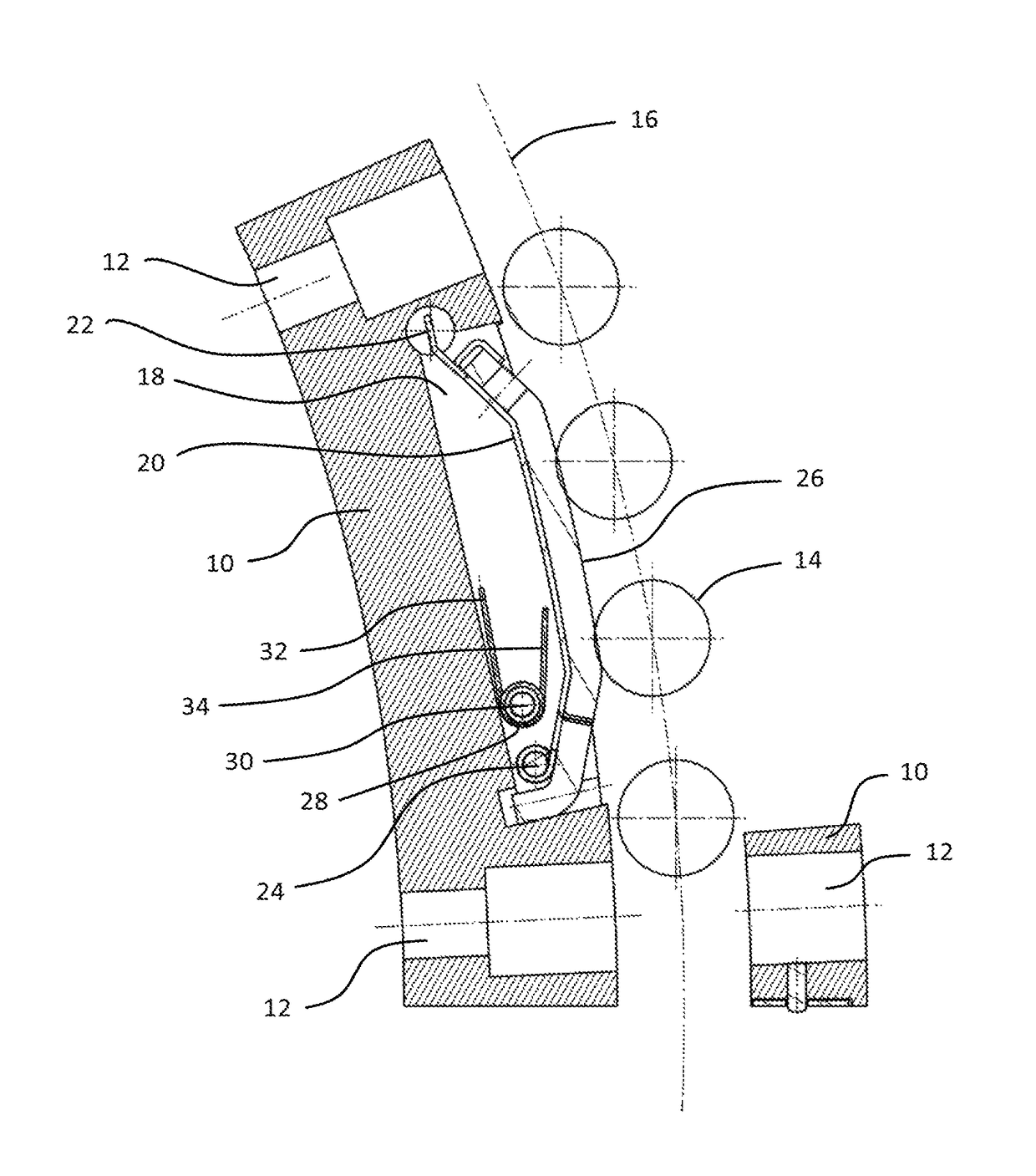
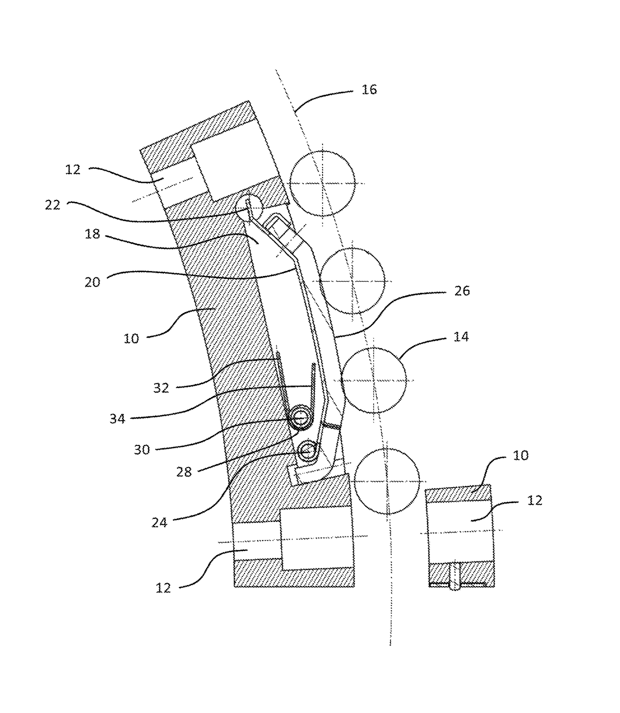
[0027]The rotor shown in the FIG. 1 comprises a die plate, not shown in the sectional view, including die bores and upper punches 14 and lower punches assigned in pairs to the die bores and circulating synchronously with the die plate. The rotor further comprises an upper punch receiver (not shown) in which the upper punches 14 are axially guided as well as a lower punch receiver (not shown) in which the lower punches are axially guided. The rotor comprises an upper control cam which controls the axial movement of the upper punches 14 passing through the upper control cam, as well as a lower control cam (not shown) which controls the axial movement of the lower punches passing through the lower control cam. The rotor is part of a rotary press which further comprises a drive for the rotational driving of the rotor as well as at least one filling station comprising at least one filling device for filling the bores with material to be compressed. At least one pressing station comprisin...


PUM

PropertyMeasurementUnit
constant forceaaaaaaaaaa
forceaaaaaaaaaa
movementaaaaaaaaaa

Abstract

A rotor for a rotary press comprising a die plate having die bores and upper punches and lower punches assigned in pairs to the die bores, circulating synchronously with the die plate An upper punch receiver is configured to axially guide the upper punches and a lower punch receiver is configured to axially guide the lower punches. An upper control cam is configured to control the axial movement of the upper punches passing through the upper control cam and a lower control cam is configured to control the axial movement of the lower punches passing through the lower control cam.

Description

CROSS REFERENCE TO RELATED APPLICATION[0001]This application is based upon and claims priority under relevant sections of 35 U.S.C. § 119 to German Patent Application No. 10 2015 105 936.3, filed Apr. 17, 2015, the entire contents of which are hereby incorporated by reference.BACKGROUND OF THE INVENTION[0002]The upper and lower punches of the rotors of rotary presses have to be lubricated with a suitable lubricant, for example a lubricating oil. This generally takes place via a contact part which is in contact with the region of the upper or respectively lower punches to be lubricated. The contact part may consist, for example, of a felt which is soaked in the lubricant. It is known to arrange the contact part used for the lubrication in the region of a control cam portion of the upper or respectively lower control cam of the rotor. For effective lubrication, the position of the contact part relative to the upper or respectively lower punches passing through the contact part is cruc...

Claims


Application Information

Patent Timeline
Patent Type & Authority Patents(United States)
IPC IPC(8): B30B11/08B29C43/08B30B15/00B29C43/04B29C43/58B29C43/50B29C43/34B29C43/32B29C37/00
CPCB30B15/0011B29C43/04B29C43/32B29C43/34B29C43/50B29C43/58B30B15/0088B30B11/08B29C2043/5808B29C43/08B29C2037/92B29C2043/046B29C2043/3288F16N7/14
Inventor LUEDEMANN, STEFAN
Owner FETTE COMPACTING GMBH
Why Eureka
Try Eureka