Escapement for a timepiece with optimized torque transmission

a technology of torque transmission and escapement, which is applied in the field of escapement with optimized torque transmission, can solve the problems of not being optimized at all, compromising and affecting the performance of the escapemen

Active Publication Date: 2020-02-27
RICHEMONT INT
View PDF0 Cites 1 Cited by
  • Summary
  • Abstract
  • Description
  • Claims
  • Application Information

AI Technical Summary

Benefits of technology

[0020]Advantageously, the form of at least one part of each of said impulsion surfaces observes said relationship, with the effect that the transmission of torque is constant for each pallet.
[0021]Advantageously, the escapement wheel includes teeth having convex impulsion surfaces. The transition between the various phases is thus smooth, which prevents the pallet from lifting-off from the wheel during the cycle.

Problems solved by technology

Although these simple forms are easy to manufacture, the transmission of torque varies throughout the impulsion phase, which is detrimental to the performance of the escapement.
Furthermore, such plane impulsion surfaces often give rise to a lifting-off of the pallet, in particular when it performs the transition from the impulsion phase on the pallet to the impulsion phase on the tooth, which similarly compromises the performance of the escapement.
Although this certainly represents an improvement in relation to planar impulsion surfaces, the form chosen does not eliminate the variations in the transmission of torque.
In addition, the convex part at the start of the impulsion surface exhibits an entirely conventional radius of curvature, which results from the current manufacturing processes, and has not been optimized at all.

Method used


Image

  • Escapement for a timepiece with optimized torque transmission
  • Escapement for a timepiece with optimized torque transmission
  • Escapement for a timepiece with optimized torque transmission

Examples


Embodiment Construction

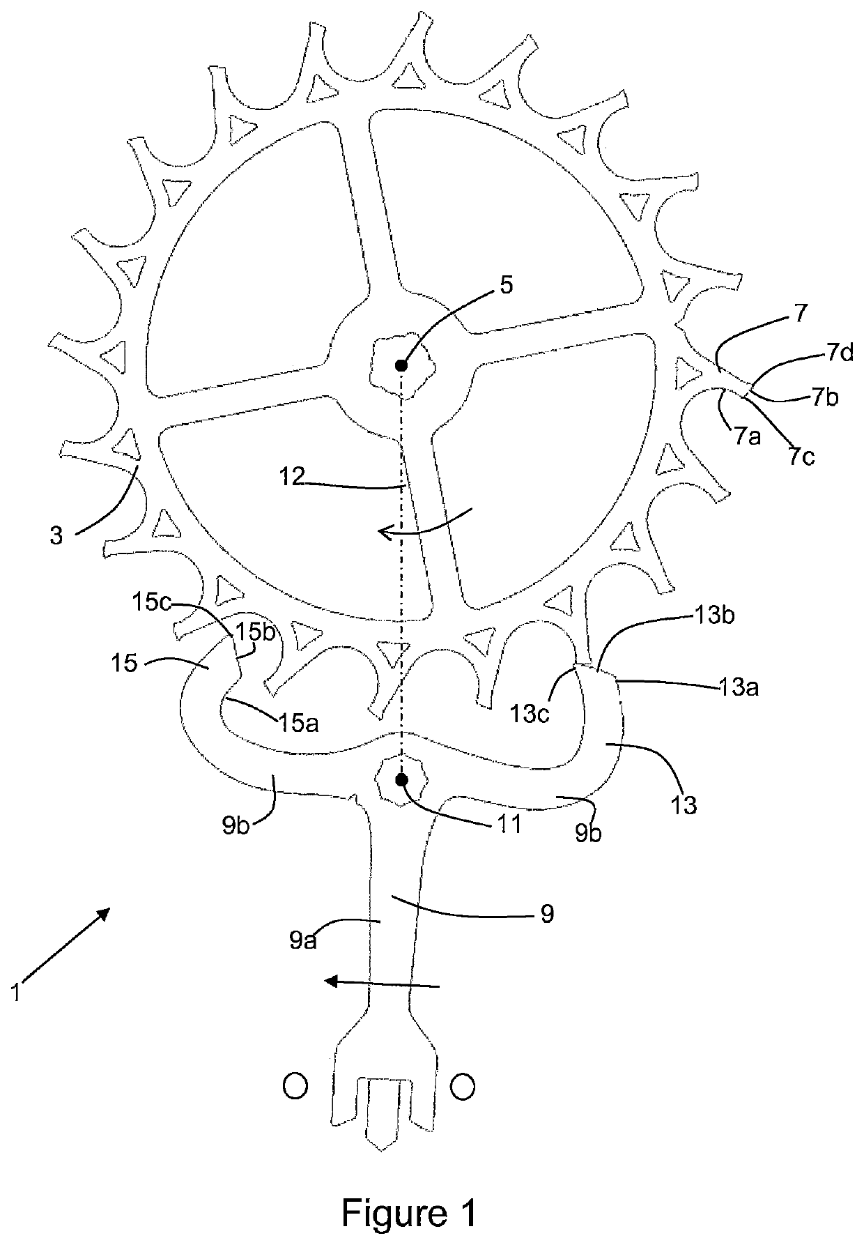
[0048]FIG. 1 depicts an escapement 1 according to the invention. This escapement 1 embodies the overall form of a Swiss anchor escapement, in which each pallet participates in providing an impulsion to the regulating member.

[0049]As generally known, the escapement comprises an escapement wheel 3, arranged to be driven by a power source, not depicted here. This power source may be a mainspring or an electric motor, for example, which is kinematically linked with the escapement wheel 3 by means of a going train (likewise not depicted).

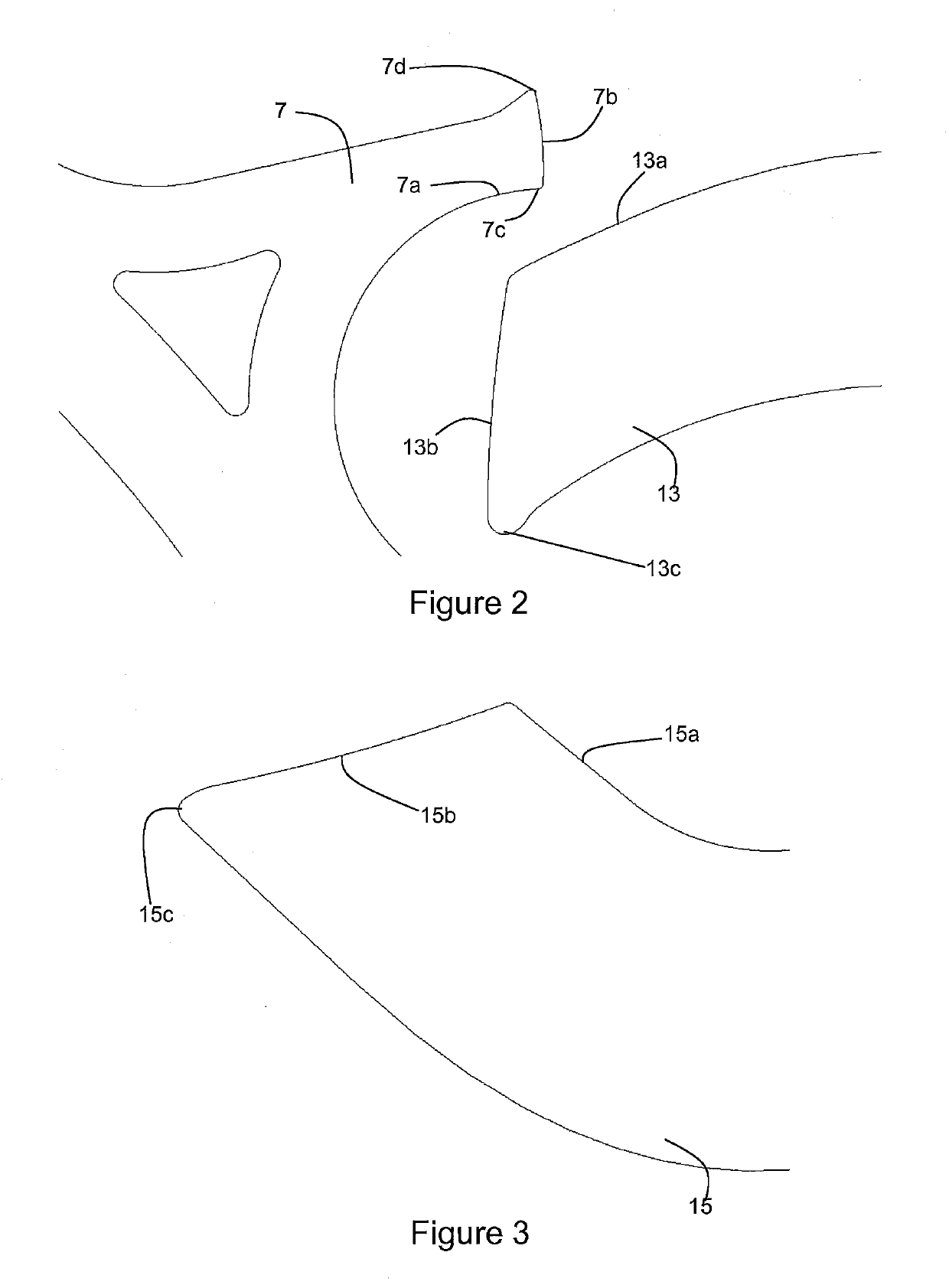
[0050]The escapement wheel 3 is mounted in a pivotable manner on an arbor (not depicted), of which the theoretical axis is indicated by the reference sign 5. In the variant depicted here, the teeth of the escapement wheel 7 each include an upstream surface 7a, which interacts with the pallets when the escapement wheel 3 is blocked, and an impulsion surface. However, the invention is applicable to other forms of escapement wheel, for example to pointed te...


PUM


Abstract

An escapement for a timepiece, comprising: —an escapement wheel pivotally mounted around a corresponding axis of rotation and intended to be driven by a drive source, said escapement wheel comprising a plurality of teeth; —a pallet fork pivotably mounted around a corresponding axis of rotation, said pallet fork comprising an entry pallet and an exit pallet, each pallet comprising a rest face arranged to block the escapement wheel, as well as a pulse face arranged to interact with the escapement wheel in order to transmit the pulses received from the latter to a regulating member arranged to perform oscillations, said pallet fork being arranged to free the escapement wheel periodically under the control of the regulating member, characterized in that at least one of the pulse faces is shaped in such a way that, on at least one portion of the pulse face, and considered at each point of contact (C′) between the escapement wheel and the pulse face, the tangent of the pulse face intersects the center-to-center distance between the escapement wheel and the pallet fork according to an angle (αorientation) that observes a particular relation.

Description

TECHNICAL FIELD[0001]The present invention relates to the field of watchmaking. It concerns, more particularly, an escapement with optimized torque transmission.BACKGROUND ART[0002]A traditional escapement, such as a Swiss anchor escapement, an English anchor escapement, a Daniels escapement or similar, includes an anchor which blocks an escapement wheel in an intermittent manner and transmits energy from the going train to the regulating member when the wheel is released. Oscillations of the regulating member, such as a balance wheel and hairspring, actuate the anchor lever in order to perform this periodic release of the escapement wheel and to supply an impulsion once more to the regulating member in order to maintain its oscillations.[0003]To this end, the anchor includes at least two pallets, one of which—the entry pallet—being situated upstream in relation to the direction of rotation of the escapement wheel, and the other—the exit pallet—being situated downstream. On each hal...

Claims


Application Information

Patent Timeline
Patent Type & Authority Applications(United States)
IPC IPC(8): G04B15/14G04B15/08
CPCG04B15/14G04B15/08
Inventor HERAUD, ALEXISMOLINA, VALENTIN
Owner RICHEMONT INT
Why Eureka
Try Eureka