Eureka AIR delivers breakthrough ideas for toughest innovation challenges, trusted by R&D personnel around the world.

Optical disc apparatus and discriminating method for kind of objective lenses

a technology of optical discs and discriminating methods, applied in the field of optical disc apparatuses, can solve the problems of insufficient reproduction or recording of information, and increased costs

Inactive Publication Date: 2010-11-23
FUNAI ELECTRIC CO LTD
View PDF8 Cites 0 Cited by
  • Summary
  • Abstract
  • Description
  • Claims
  • Application Information

AI Technical Summary

Benefits of technology

[0018]According to this structure it becomes possible to perform the discrimination of kind of the objective lens without arranging a detecting device separately. Further, because the discriminating portion has a structure discriminating kind of the objective lens by utilizing spherical aberration depending on design of the objective lens, it becomes possible to perform the discrimination of kind of the objective lens without receiving effect due to variation in degree of reflection of the optical recording medium. Therefore, it becomes possible to provide an optical disc apparatus including a plurality of kinds of the objective lenses, changing the objective lenses to utilize in response to kind of an optical recording medium, and further able to prevent an improper setting of the objective lens disposed in a light path without arranging newly a detecting device.
[0020]According to this structure, it becomes possible to provide an optical disc apparatus easily able to prevent improper setting of an objective lens disposed in a light path from an optical disc apparatus structured conventionally.
[0022]According to this structure because the structure discriminates kind of an objective lens by utilizing a spherical aberration compensating element which is included in an optical pickup device, it becomes possible to perform discrimination of kind of the objective lens without necessity to arrange a detecting device separately, and without effect due to variation in degree of reflection of an optical recording medium. Therefore, it becomes possible to provide a discriminating method for kind of the objective lens which can discriminate correctly kind of the objective lens disposed in a light path in an optical pickup device which includes a plurality of kinds of objective lenses without arranging newly a detecting device.

Problems solved by technology

However, because such structure causes problems that size of the optical disc apparatus becomes large and the like, it is usual to employ a structure in that one optical pickup device can perform reproducing or the like of information for a plurality of kinds of the optical recording media.
However, such an objective lens is difficult to design and causes a problem of cost rising.
However, when this kind of method is employed, there may be a case that the change of the objective lenses is not performed because the repulsive force is so strong that objective lenses bounce.
When reproducing of information from the optical recording medium or recording of information to the optical recording medium is performed in a state that the objective lens is not the primary objective lens in the light path, reproducing or recording of information is not performed properly and there is a possibility that various troubles happen in the optical disc apparatus.
Therefore, it causes problem of cost increase, problem of weight increase of a movable member to enable the movement of the objective lens and the like.
Further in a case where discrimination of kind of an objective lens disposed in a light path is performed by utilizing the structure disclosed in JP-A-2003-099958, it is not necessary to arrange newly a detecting device unlike cases of JP-A-H09-305980 and JP-A-H10-198969, however, there may be a problem that discrimination of kind of an objective lens is erroneously performed because degree of reflection of an optical recording medium varies widely due to nonuniformity of the optical recording medium when it is manufactured and the like.

Method used


Image

  • Optical disc apparatus and discriminating method for kind of objective lenses
  • Optical disc apparatus and discriminating method for kind of objective lenses
  • Optical disc apparatus and discriminating method for kind of objective lenses

Examples


Embodiment Construction

[0031]Hereinafter, contents of the present invention will be described in detail with reference to the attached drawings. However, the embodiments described here are merely examples, and the present invention is not limited to the embodiments described here.

[0032](Structure of an Optical Disc Apparatus)

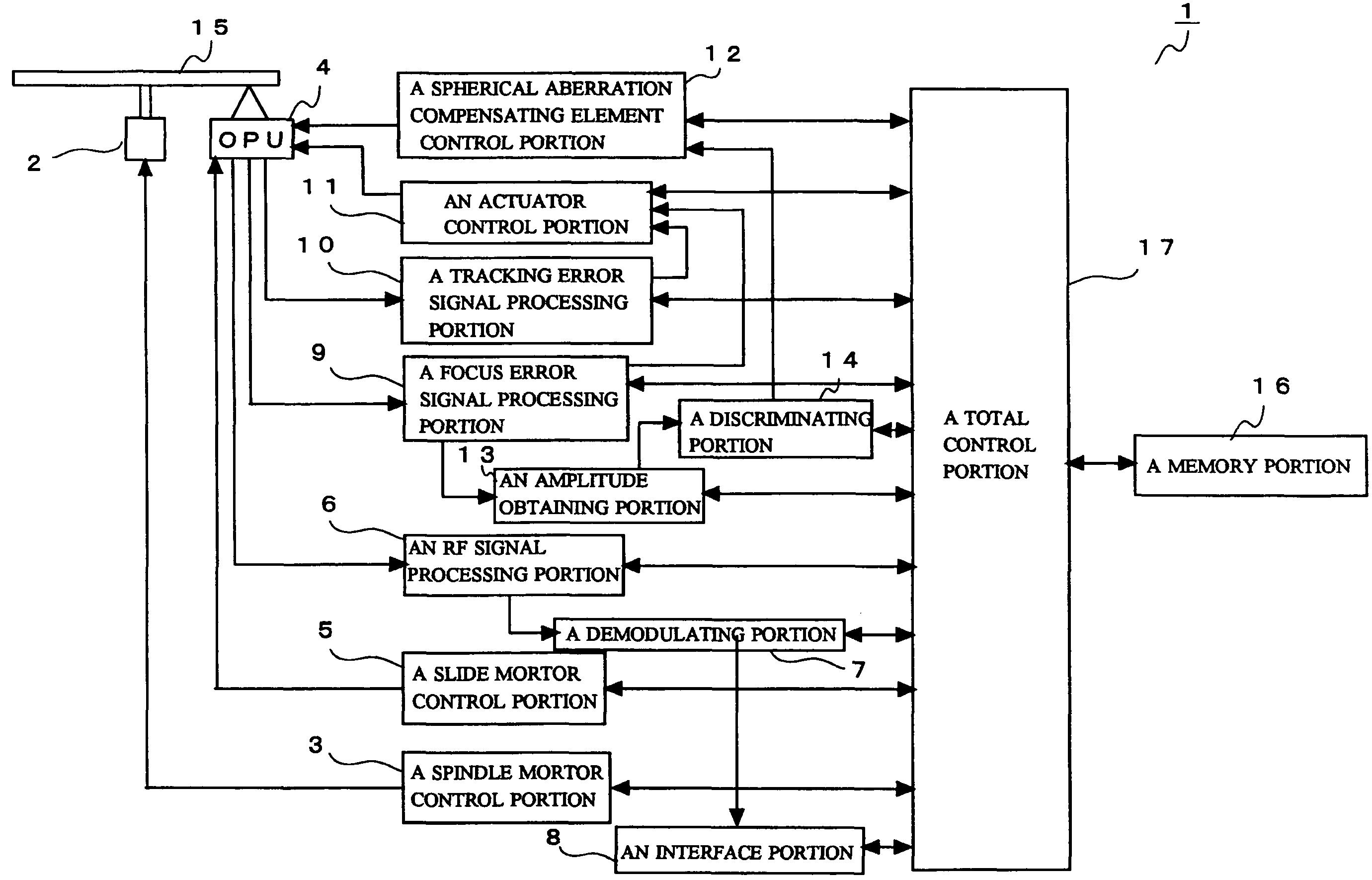
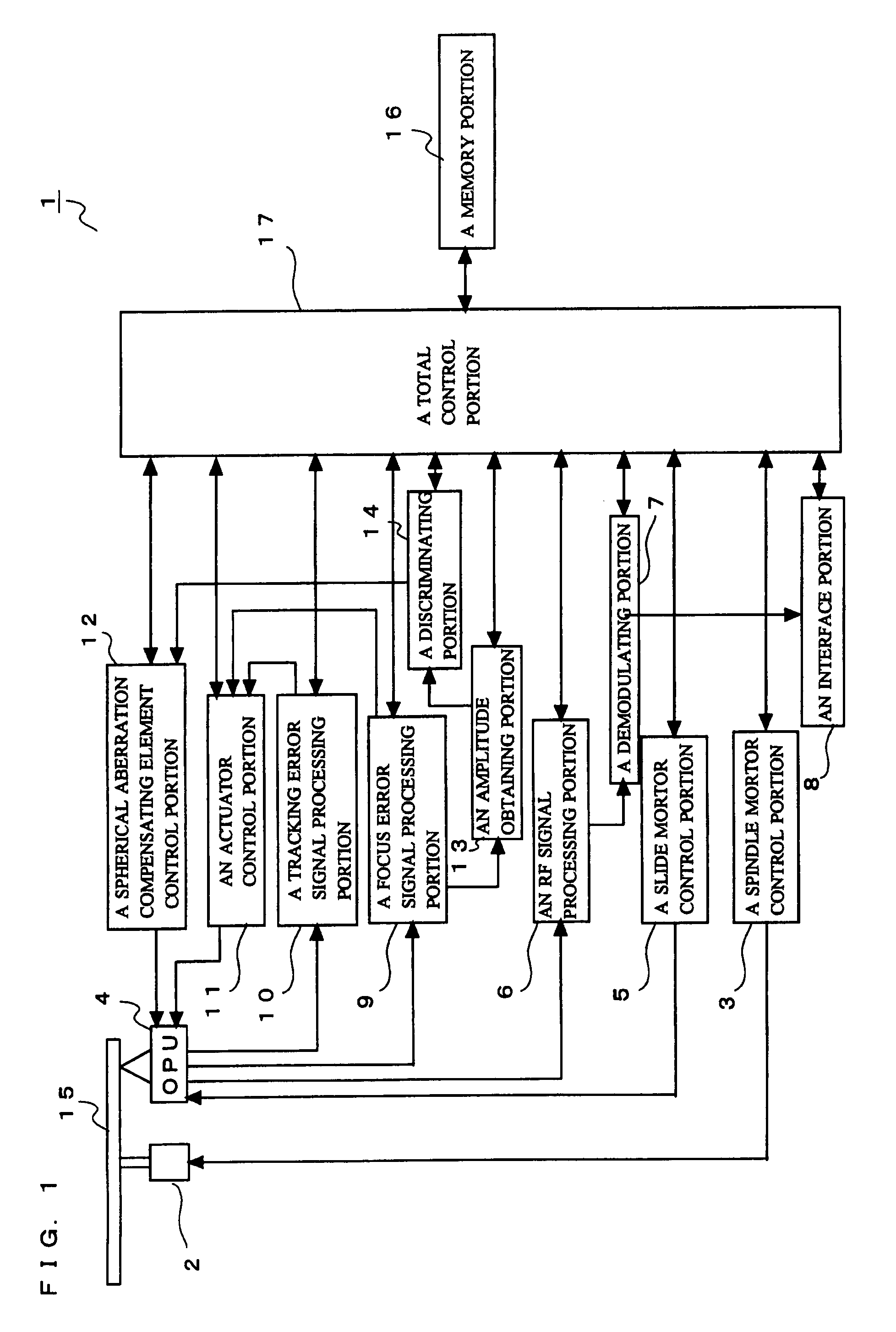
[0033]First, structure of an optical disc apparatus according to the present embodiment will be described. FIG. 1 is a block diagram to show a structure of an optical disc apparatus according to the present embodiment. The optical disc apparatus 1 is configured to be possible to reproduce information of an optical disc (an optical recording medium) 15 and record information to the optical disc 15. Here, kinds of the optical disc 15 to / of which the optical disc apparatus 1 can perform recording or reproducing, are a CD, a DVD, and a BD.

[0034]Reference numeral 2 designates a spindle motor, and the optical disc 15 is held detachably on a chuck portion (not shown) which is disposed on an ...


PUM

PropertyMeasurementUnit
wavelengthaaaaaaaaaa

Abstract

An optical disc apparatus includes an amplitude obtaining portion receiving S shaped waveform information of focus error signal from a focus error signal processing portion to obtain amplitude of the S shaped waveform and a discriminating portion discriminating kind of objective lens disposed in a light path of an optical pickup device. The discriminating portion changes controlled variable of a spherical aberration compensating element into a plurality of prescribed control values, and obtains the amplitude of S shaped waveform from an amplitude obtaining portion for each of the control values. Then the discriminating portion performs discrimination of kind of the objective lens disposed in the light path based on that a rate of change of the amplitude of S shaped waveform to change of controlled variable of the spherical aberration compensating element is different in response to kind of the objective lens.

Description

[0001]This application is based on Japanese Patent Application No. 2006-247572 filed on Sep. 13, 2006, and the contents of which are hereby incorporated by reference.BACKGROUND OF THE INVENTION[0002]1. Field of the Invention[0003]The present invention relates to an optical disc apparatus which includes a plurality of objective lenses in an optical pickup device and changes the objective lenses to utilize in response to kind of an optical recording medium, especially, the present invention relates to the optical disc apparatus having a structure which can prevent an improper setting of the objective lenses. Further, the present invention relates to a discriminating method for kind of the objective lenses in the optical pickup device which changes a plurality of the objective lenses to utilize.[0004]2. Description of Related Art[0005]Optical recording media including a compact disc (hereinafter referred to as “a CD”) and a digital versatile disc (hereinafter referred to as “a DVD”) ha...

Claims


Application Information

Patent Timeline
Patent Type & Authority Patents(United States)
IPC IPC(8): G11B7/135
CPCG11B7/1369G11B7/1374G11B7/13925G11B2007/0006
Inventor HAYASHI, TOSHIYUKI
Owner FUNAI ELECTRIC CO LTD
Why Eureka
Eureka Blog
Learn More