Engine start control apparatus for hybrid vehicle

a technology of hybrid vehicles and start control apparatus, which is applied in the direction of engines/engines, propulsion using engine-driven generators, transportation and packaging, etc., can solve the problems of insufficient rise in engine revolutions, restricted obtained rotational force, so as to increase electric motor travel range, fuel consumption, and increase the effect of electric motor travel rang

Active Publication Date: 2016-04-05
TOYOTA JIDOSHA KK
View PDF14 Cites 8 Cited by
  • Summary
  • Abstract
  • Description
  • Claims
  • Application Information

AI Technical Summary

Benefits of technology

[0018]According to the engine start control apparatus for a hybrid vehicle according to the first invention, when the direct injection engine is started up in a state where a prescribed second cylinder of a plurality of cylinders is positioned at top dead center, the engine revolutions are raised by producing a first explosion in a first cylinder situated before the second cylinder in an ignition sequence, the first cylinder being in an expansion stroke and an exhaust valve thereof not being open, by directly injecting fuel into the first cylinder and igniting the fuel, and furthermore assistance in increasing the engine revolutions is started by transmitting assist torque output from the rotary machine to the direct injection engine via the clutch, in a peak section immediately after the engine revolutions start to increase. Therefore, in the hybrid vehicle which connects and disconnects a direct injection engine with respect to a power transmission path by a clutch, the direct injection engine which has stopped can be started by using a sufficient required assist torque. Furthermore, as a result of this, the consumption of the electrical energy of the accumulator apparatus in starting the direct injection engine is reduced, the electrical energy for engine starting which is to be reserved in the accumulator apparatus at all times is reduced, and therefore the electric motor travel range is increased and the fuel consumption of the vehicle is improved appropriately.
[0025]According to the engine start control apparatus for a hybrid vehicle according to the eighth invention, when rotation of a crank shaft of the direct injection engine is not raised by a first explosion in the first cylinder, the engine revolutions are increased by transmitting assist torque output from the rotary machine to the direct injection engine via the clutch, and therefore, if, for any reason, a rise in the engine revolutions cannot be obtained by beginning an ignition start, then the engine revolutions are increased by transmitting the assist torque output from the rotary machine to the direct injection engine via the clutch, thus guaranteeing the responsiveness of the starting operation.

Problems solved by technology

In this state, the air volume in the cylinder performing the initial explosion is not necessarily sufficient, the rotational force obtained by the initial explosion is small, and the rise in the engine revolutions may be insufficient.
However, if the raising of the rotational speed during start-up of the direct injection engine is assisted by driving the crank shaft using a rotary machine, then the amount of electrical energy consumed by the accumulator device when starting the direct injection engine is large, and therefore electrical energy for starting the engine must always be reserved in the accumulator device, thereby restricting the electric motor travel range, and presenting an obstacle to improvement in the fuel consumption of the vehicle.
For example, in the case of an eight-cylinder engine, if the crank shaft stops near the compression TDC, then the preceding cylinder has a crank angle of approximately 90° and is still in the expansion stroke, which means that ignition starting is possible, but since the exhaust valve will soon open and the cylinder will enter the exhaust stroke (for example, near 120°), then sufficient rotational energy cannot be expected, the raising of the engine revolutions is weak, and therefore a large assist torque is required for starting.

Method used


Image

  • Engine start control apparatus for hybrid vehicle
  • Engine start control apparatus for hybrid vehicle
  • Engine start control apparatus for hybrid vehicle

Examples


embodiments

[0039]Embodiments of the invention are described in detail below with reference to the drawings.

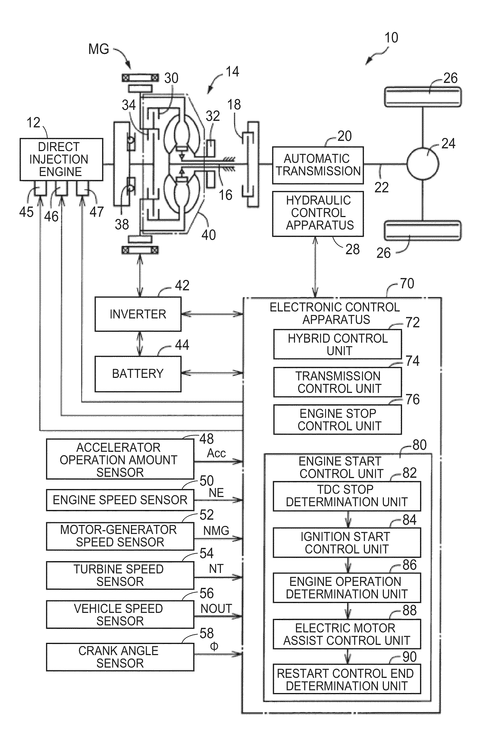
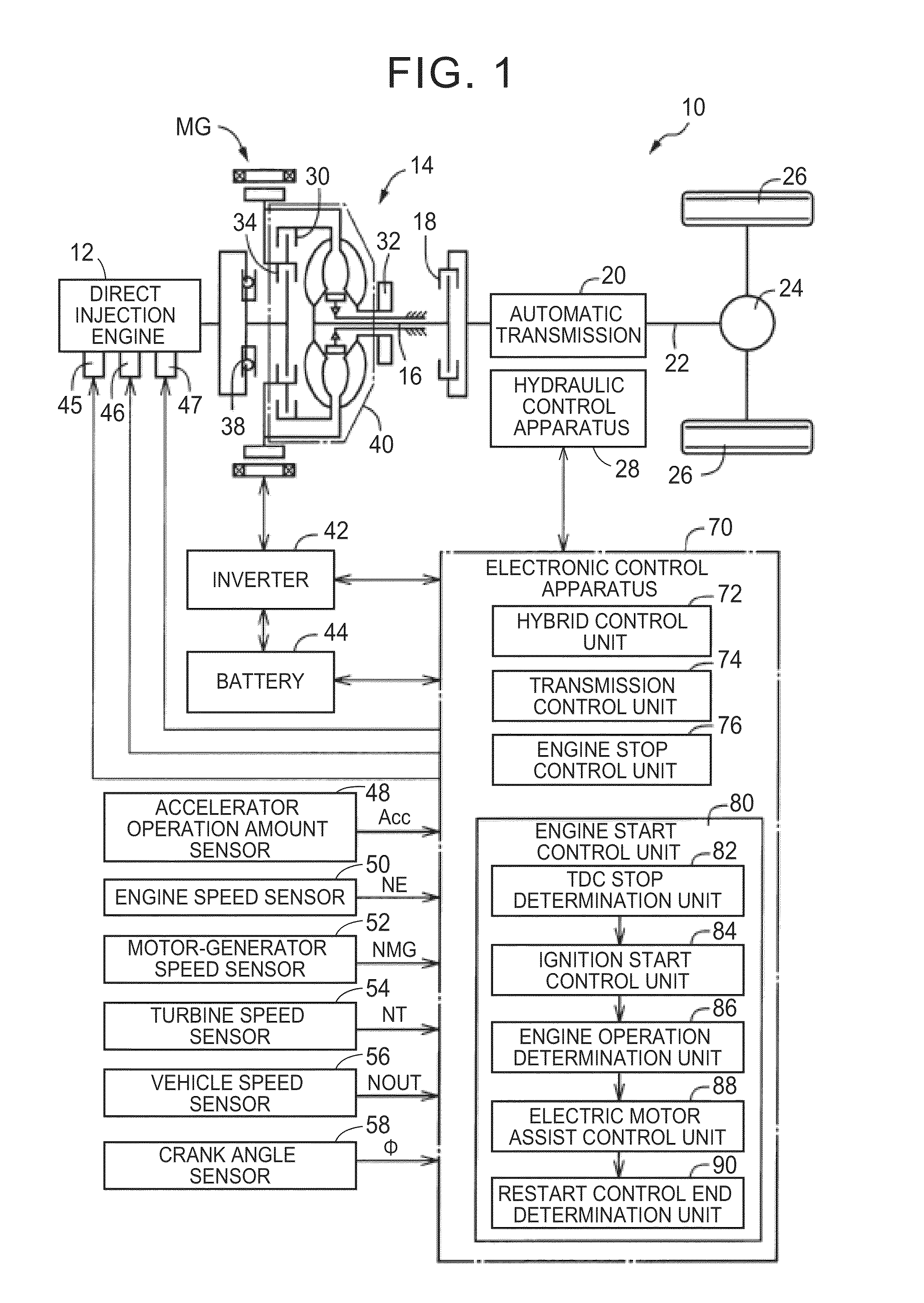
[0040]FIG. 1 is a schematic diagram including a skeleton diagram of a drive system of a hybrid vehicle 10 to which the invention is desirably applied. This hybrid vehicle 10 includes, as drive power sources for travel, a direct injection engine 12 that directly injects fuel into the cylinders, and a motor-generator MG which functions as an electric motor and an electric generator. The output of the direct injection engine 12 and the motor-generator MG is transmitted from a torque converter 14, which is a fluid-type transmission device, via a turbine shaft 16 and a C1 clutch 18, to an automatic transmission 20, and is then further transmitted via an output shaft 22 and differential gear apparatus 24, to left and right drive wheels 26. The torque converter 14 is provided with a lock-up clutch 30 which directly couples a pump impeller and a turbine impeller, and furthermore an oil pump 32 is...


PUM


Abstract

In a hybrid vehicle, when using an ignition start to start a direct injection engine while any one of the cylinders has stopped near top dead center, engine revolutions are raised by producing a first explosion in a first cylinder, which is situated before a second cylinder in an ignition sequence and is in an expansion stroke and in which an exhaust value is not open, by directly injecting fuel into the first cylinder and igniting the fuel. Furthermore, assistance in increasing the engine revolutions is started by transmitting assist torque output from a motor-generator to the direct injection engine via a clutch, in a peak section immediately after the start of increase in the engine revolutions. The stopped direct injection engine can be started using a sufficient required assist torque, namely, electrical energy, whereby the electrical energy for engine starting that is always reserved in a battery (accumulator apparatus) is reduced and therefore a travel range is increased and vehicle fuel consumption is improved appropriately.

Description

CROSS-REFERENCE TO RELATED APPLICATIONS[0001]This is a national phase application based on the PCT International Patent Application No. PCT / JP2011 / 069793 filed on Aug. 31, 2011, the entire contents of which are incorporated herein by reference.TECHNICAL FIELD[0002]The invention relates to an engine start control apparatus for a hybrid vehicle provided with a direct injection engine.BACKGROUND ART[0003]There is a conventional hybrid vehicle which has a direct injection engine that injects fuel directly into cylinders, a clutch that engages and disengages (connects and disconnects) the direct injection engine with respect to a power transmission path, and a rotary machine which functions as at least an electric motor, wherein the direct injection engine and the rotary machine can be used as sources of drive power for travel. The hybrid vehicle described in Patent Document 0.1 is one example thereof. In a hybrid vehicle of this kind, direct coupled start technology has been proposed, n...

Claims


Application Information

Patent Timeline
Patent Type & Authority Patents(United States)
IPC IPC(8): F02B17/00B60K6/48B60K6/54B60W10/02B60W10/06B60W10/08B60W20/00B60L50/16
CPCF02B17/005B60K6/48B60K6/54B60W10/02B60W10/06B60W10/08B60W20/00B60W20/40B60W2510/0685B60Y2300/432B60Y2300/48Y02T10/6221Y02T10/6286Y02T10/62Y02T10/12B60W20/15
Inventor KOJIMA, SUSUMUNAKANISHI, NAOKIIDESHIO, YUKIHIKO
Owner TOYOTA JIDOSHA KK
Why Eureka
Try Eureka