
Incisor tooth or canine tooth, and set of teeth, and method for producing and incisor tooth or canine tooth

a technology for canine teeth and incisor teeth, applied in the field of anterior teeth, can solve the problems of uneven tooth effect, unsatisfactory esthetic point of view, and poor sprue, and achieve the effects of good anchoring, easy production, and good tolerance of inner stresses

Active Publication Date: 2016-04-12
IVOCLAR VIVADENT AG
View PDF25 Cites 2 Cited by
  • Summary
  • Abstract
  • Description
  • Claims
  • Application Information

AI Technical Summary

Benefits of technology

The invention allows for a dental design that improves the optical properties of teeth, especially canine teeth, by using a layer of cutting-edge material that is attached to dentine material. The cutting-edge material has projections and irregularities that are at a certain height, which is different than the original height of the tooth. The height of the irregularities can be very small or much larger, depending on the thickness of the cutting-edge material. This design prevents washed-out or too "technical" impressions. The invention also allows for a larger layer thickness for the cutting-edge materials, which makes the design more mechanically stable and reduces chipping. The solution is particularly well-suited for ceramic teeth and combining dentine material with a softer cutting-edge material can provide a natural appearance and reduce impact on the antagonist of the restored tooth.

Problems solved by technology

However, this means that the tooth has a rather uneven effect specifically in the incisal area.
Such sprues are not very satisfactory from the technical point of view and also unsatisfactory from the esthetic point of view.
Mention may be made here of the known painting technique, which is still used regularly even today, even though it is very much dependent on the skill of the dental technician and is labor-intensive.
This solution, however, is extremely difficult to implement on account of the technical difficulties involved, especially since it is necessary to establish an exact reference point, which is a spatial one and is therefore difficult to define.
Typically, the removal of mold halves with undercuts typically requires the provision of complicated slides, which also impair the precision.

Method used


Image

  • Incisor tooth or canine tooth, and set of teeth, and method for producing and incisor tooth or canine tooth
  • Incisor tooth or canine tooth, and set of teeth, and method for producing and incisor tooth or canine tooth
  • Incisor tooth or canine tooth, and set of teeth, and method for producing and incisor tooth or canine tooth

Examples


Embodiment Construction

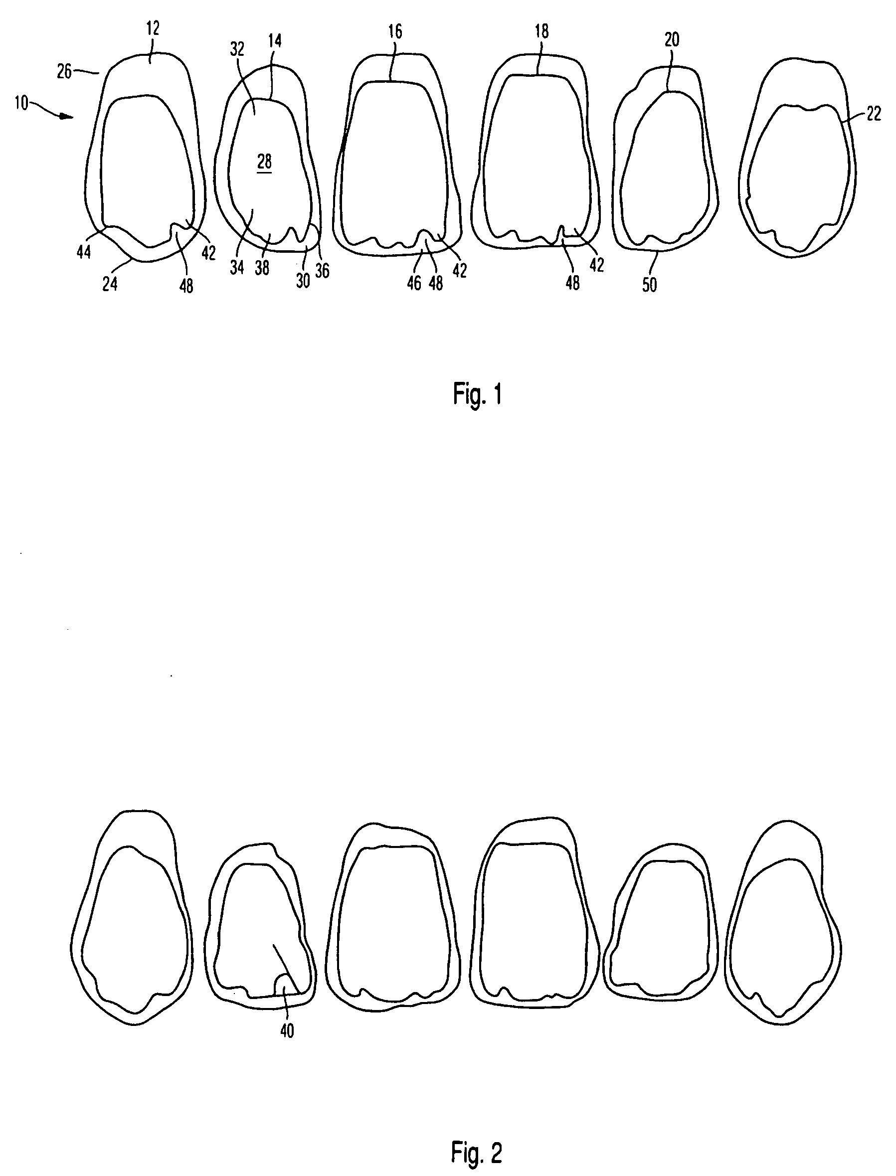
[0028]FIG. 1 shows, by way of example, one embodiment of a set of teeth according to the invention for the upper jaw, with four incisor teeth and two canine teeth. The set 10 of teeth comprises a canine tooth 12, four incisor teeth 14, 16, 18 and 20, and a further canine tooth 22. The view shows in each case a section through the tooth in the area of its greatest extent. Each tooth has an incisal cutting edge 24 and extends between this cutting edge and the basal end 26 in a manner known per se from the basic form.

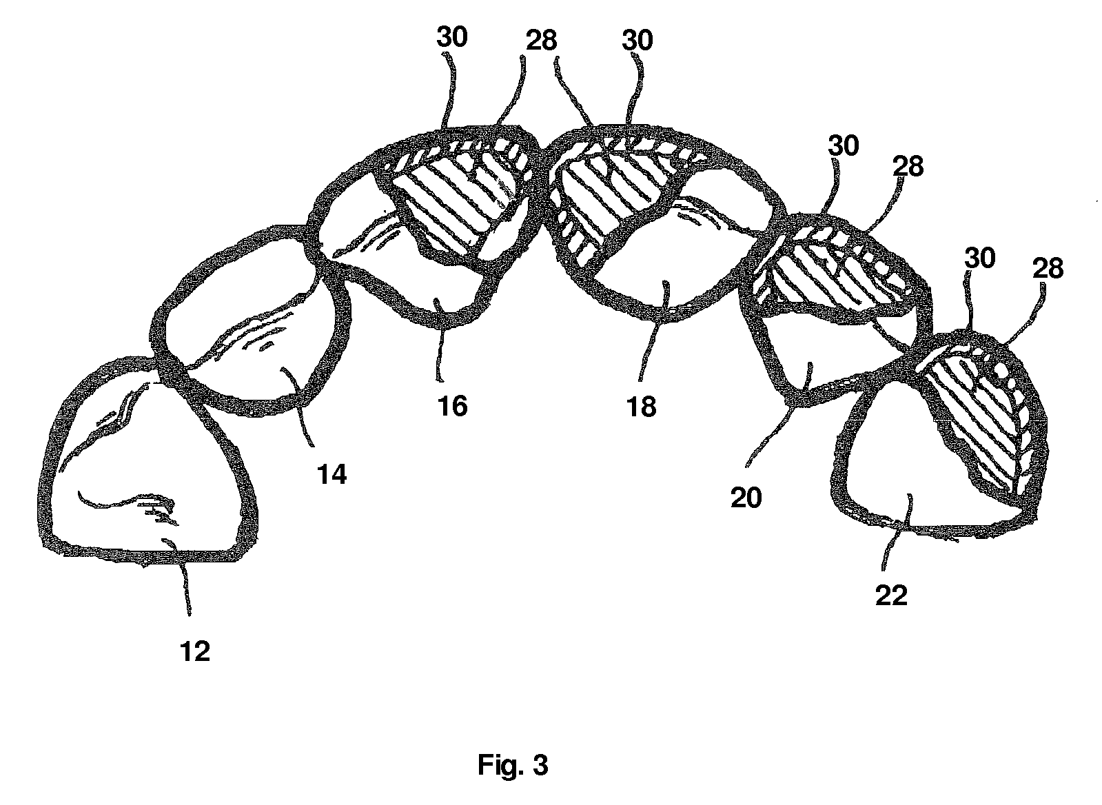
[0029]For simplicity, the incisor tooth 14, which is to be regarded as tooth II, will be considered here. The tooth 14 is basically built up of dentine material 28 which, in the illustrative embodiment shown, is completely surrounded by cutting-edge material 30. Although the cutting-edge material in the illustrative embodiments shown here extends also over the basal end 26, it will be appreciated that it is also possible to provide the dentine material there.

[0030]In the i...


PUM

PropertyMeasurementUnit
thicknessaaaaaaaaaa
thicknessaaaaaaaaaa
lengthaaaaaaaaaa

Abstract

The invention relates to an anterior tooth such as an incisor tooth or canine tooth built up in layers, with a cutting-edge material (30) at least partially covering a dentine material (28). At its occlusal end (38), the dentine material has projections (42) and / or irregularities (42, 46 and 48), which extend in the occlusal direction and correspond to 0.05 to 0.4 times the total length of a tooth.

Description

CROSS-REFERENCE TO RELATED APPLICATIONS[0001]This application claims foreign priority benefits under 35 U.S.C. §119(a)-(d) from German patent application ser. no. P 10 2007 050 439.1 filed Oct. 22, 2007.TECHNICAL FIELD[0002]The invention relates to anterior teeth such as an incisor tooth or canine tooth which is built up in layers, and more particularly to such a tooth wherein a cutting-edge material at least partially covers a dentine material, and to a method of making such a tooth.BACKGROUND OF THE INVENTION[0003]It has long been known for artificial teeth, in particular incisor teeth or canine teeth, to be built up from layers. In doing so, a cutting-edge material is built up such that it covers most of a dentine material, apart from the basal area of the dentine material. The dentine material can be joined to the cutting-edge material in any suitable way desired.[0004]Thus, it is known from DE-A1 38 27 657, for example, to first build up a basic body of dentine material and the...

Claims


Application Information

Patent Timeline
Patent Type & Authority Patents(United States)
IPC IPC(8): A61C13/09A61C13/08A61C13/097
CPCA61C13/09A61C13/081A61C13/097
Inventor FERRILLI, ANTONIO
Owner IVOCLAR VIVADENT AG
Learn More