Single technology micro-motion occupancy sensor system

a sensor system and single technology, applied in the field of occupancy sensors, can solve the problems of not being able to detect the presence of a substantially sedentary person, so as to achieve periodic reduction of delay count

Active Publication Date: 2016-04-12
FRED KATZ CONSULTING INC
View PDF5 Cites 12 Cited by
  • Summary
  • Abstract
  • Description
  • Claims
  • Application Information

AI Technical Summary

Problems solved by technology

But as suggested above, such known PIR occupancy sensor systems can miss a presence of a sedentary person, typically because when “covering” a large volumetric space or room, conventional PIR occupancy sensor systems fail to detect “small” motions of a substantially sedentary person.
Again, many conventional PIR occupancy sensor systems, particularly based on direction of the receiving port, are unable to detect small motions of a substantially sedentary person because the small motion does not cross one of the passive IR beams.
Use of Doppler sensors, however, comes with its own problems.
For example, Doppler sensors have a tendency to occasionally raise false alarms and perhaps as importantly, there is an additional cost associated with adding the Doppler sensor as they require additional transmit / receive transducer(s), amplification and detection circuitry and a controller programmed to orchestrate the system operation.

Method used


Image

  • Single technology micro-motion occupancy sensor system
  • Single technology micro-motion occupancy sensor system
  • Single technology micro-motion occupancy sensor system

Examples


Embodiment Construction

[0028]The following is a detailed description of example embodiments of the invention depicted in the accompanying drawing. The example embodiments are presented in such detail as to clearly communicate the invention and are designed to make such embodiments obvious to a person of ordinary skill in the art. However, the amount of detail offered is not intended to limit the anticipated variations of embodiments; on the contrary, the intention is to cover all modifications, equivalents, and alternatives falling within the spirit and scope of the present invention, as defined by the appended claims.

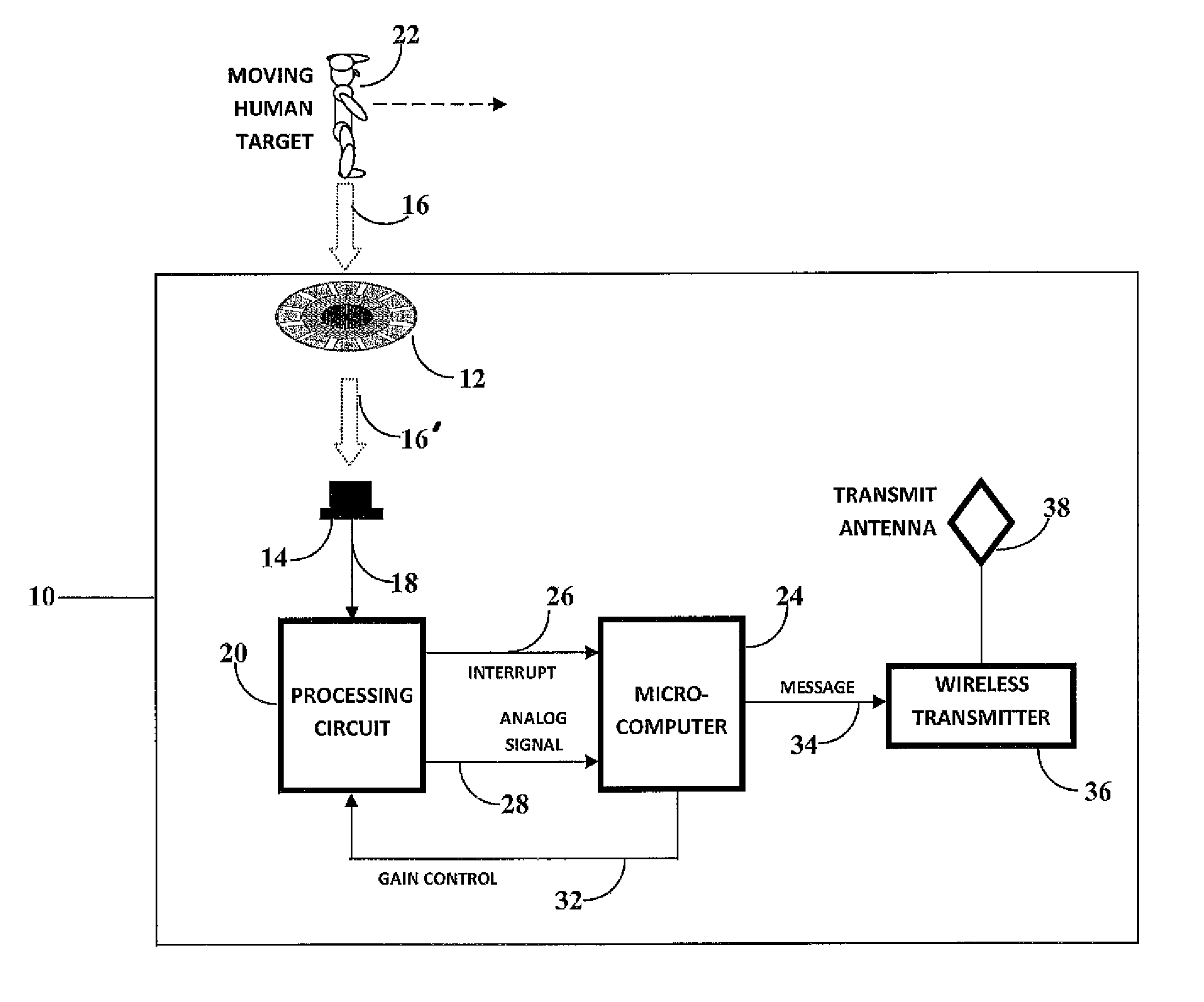
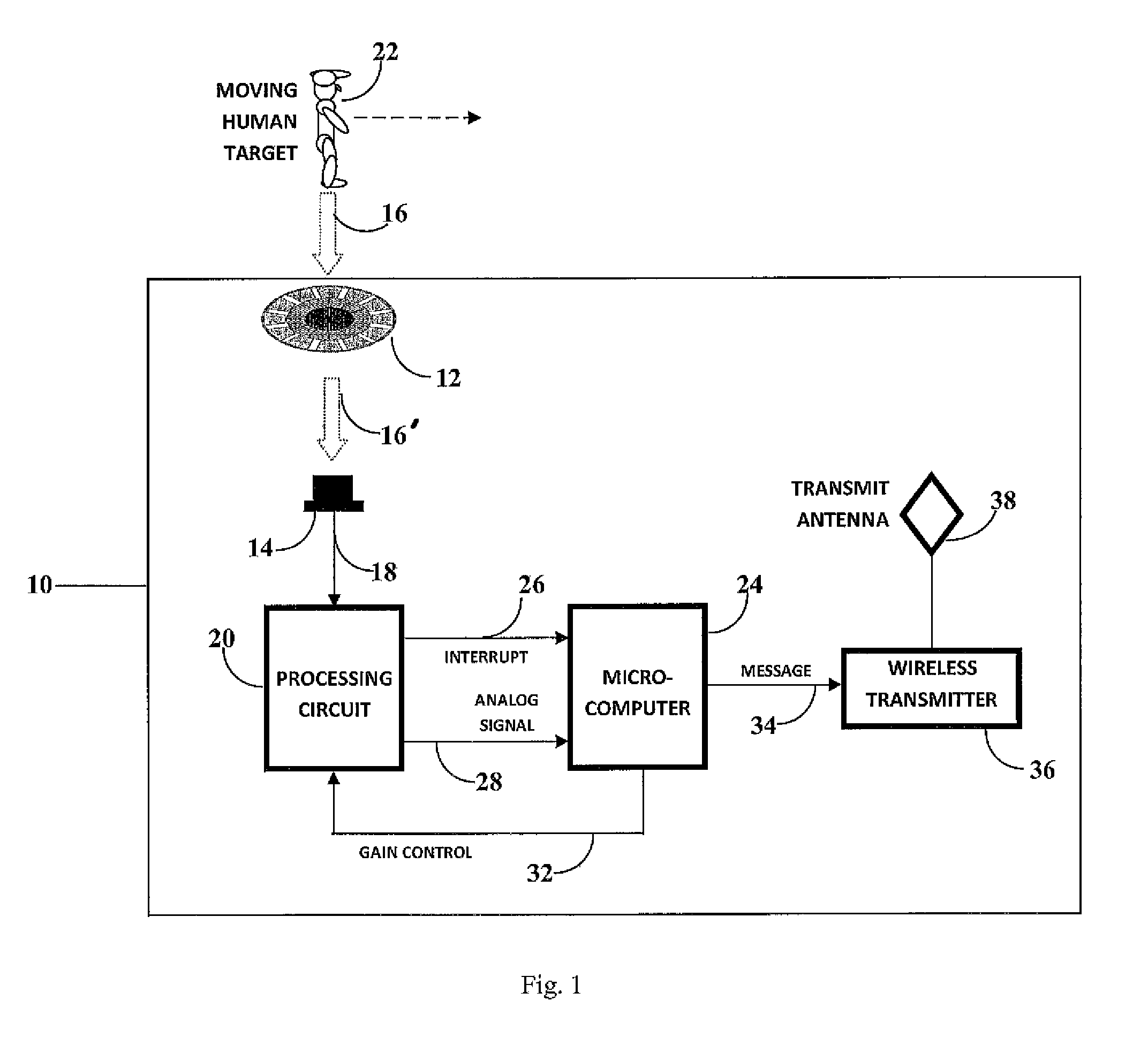
[0029]This invention provides a passive area occupancy sensor system that operates in two modes (vacant and occupied) to accurately determine a presence of a person in a room and, therefore, whether to supply of electrical power thereto, particularly in a case where a person present is substantially sedentary and likely not to be detected by known occupancy sensors and sensor systems.

[0030]I...


PUM


Abstract

A micro-motion occupancy sensor system monitors for a presence of a person in a room, in different monitoring modes, to regulate power delivery to the room. The micro-motion occupancy sensor has a multimode lens for receiving passive infrared (IR) energy and focusing the IR energy as a series of IR beams, a pyroelectric detector to receive the focused IR beams and generate an electrical signal, a processing circuit to amplify, filter and processes the electrical signal to generate an interrupt signal and an analog output signal and a controller that receives and processes the interrupt signal and the analog output signal to determine whether a person has entered a room or is maintaining their presence within the room. The controller controls the processing in a vacant mode where a person's presence is not detected and in an occupied mode when a person's presence has been detected.

Description

CROSS-REFERENCE TO A RELATED APPLICATIONS[0001]The invention described and claimed hereinbelow claims priority under 35 USC §120 from U.S. Provisional Patent Application Ser. No. 62 / 024,301, filed. Jul. 14, 2014, the contents of which are incorporated by reference herein.BACKGROUND OF THE INVENTION[0002]The invention relates broadly to occupancy sensors and more specifically to a single technology micro-motion occupancy sensor system that is sufficiently sensitive to identify a presence of a sedentary person in a room in order to control electrical power delivery to the room.[0003]Occupancy sensors were developed to determine when a person is in a predetermined volumetric space and supply electrical power thereto only if one or more persons are present. Typically, some fixed time after a last presence in the space is detected (e.g., using a motion sensor), an electrical power delivery circuit to the space is opened, which cuts off all appliances and fixtures connected thereto from t...

Claims


Application Information

Patent Timeline
Patent Type & Authority Patents(United States)
IPC IPC(8): G01J5/00G01J5/34
CPCG01J5/025G01J5/0806G01J5/0025G01J5/34G02B3/10
Inventor KATZ, FRED
Owner FRED KATZ CONSULTING INC
Why Eureka
Try Eureka