Vertebral osteosynthesis equipment

a technology of vertebral osteosynthesis and equipment, applied in the field of vertebral osteosynthesis equipment, can solve the problems of unsatisfactory existing equipment including these ligaments, unsuitable equipment type, and inconvenient use, and achieve the effect of durable connection of ligaments to connectors

Active Publication Date: 2016-04-19
MEDICREA INT SA
View PDF13 Cites 27 Cited by
  • Summary
  • Abstract
  • Description
  • Claims
  • Application Information

AI Technical Summary

Benefits of technology

[0009]The present invention therefore aims primarily to provide vertebral osteosynthesis equipment in which the strength of the connection of the ligaments to the connectors is durable.
[0010]Another aim of the invention is to provide equipment in which the force that must be exerted on a ligament to perform a derotation of a vertebra is more reduced than with the existing equipment.
[0011]One additional aim of the invention is to provide an instrument making the action exerted on the connectors easier to exert traction on a ligament.SUMMARY OF THE INVENTION

Problems solved by technology

This type of equipment is therefore not suitable when the pedicles of the vertebrae are deteriorated or the spaces are insufficient at the vertebral laminas, as is the case when the spine is greatly distracted and / or when the vertebrae are significantly pivoted and / or deformed.
This type of equipment is also not suitable when it is necessary to perform a fairly significant “derotation” of one or more vertebrae, i.e. to pivot said vertebra(e) around themselves on the cervico-caudal axis so as to resituate them in normal anatomical positions.
The existing equipment including these ligaments appears not to be fully satisfactory.
In fact, the strength of the connection of the ligaments to the connectors appears uncertain over time.
Furthermore, the force that must be exerted on a ligament to perform a derotation of a vertebra is significant, which makes that derotation operation relatively complex, difficult and long.
Furthermore, the instruments used to act on the connectors when traction is exerted are not optimal.

Method used


Image

  • Vertebral osteosynthesis equipment
  • Vertebral osteosynthesis equipment
  • Vertebral osteosynthesis equipment

Examples


Embodiment Construction

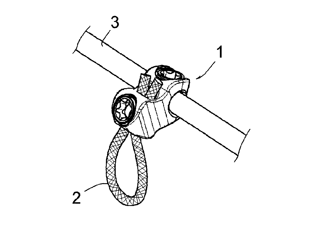
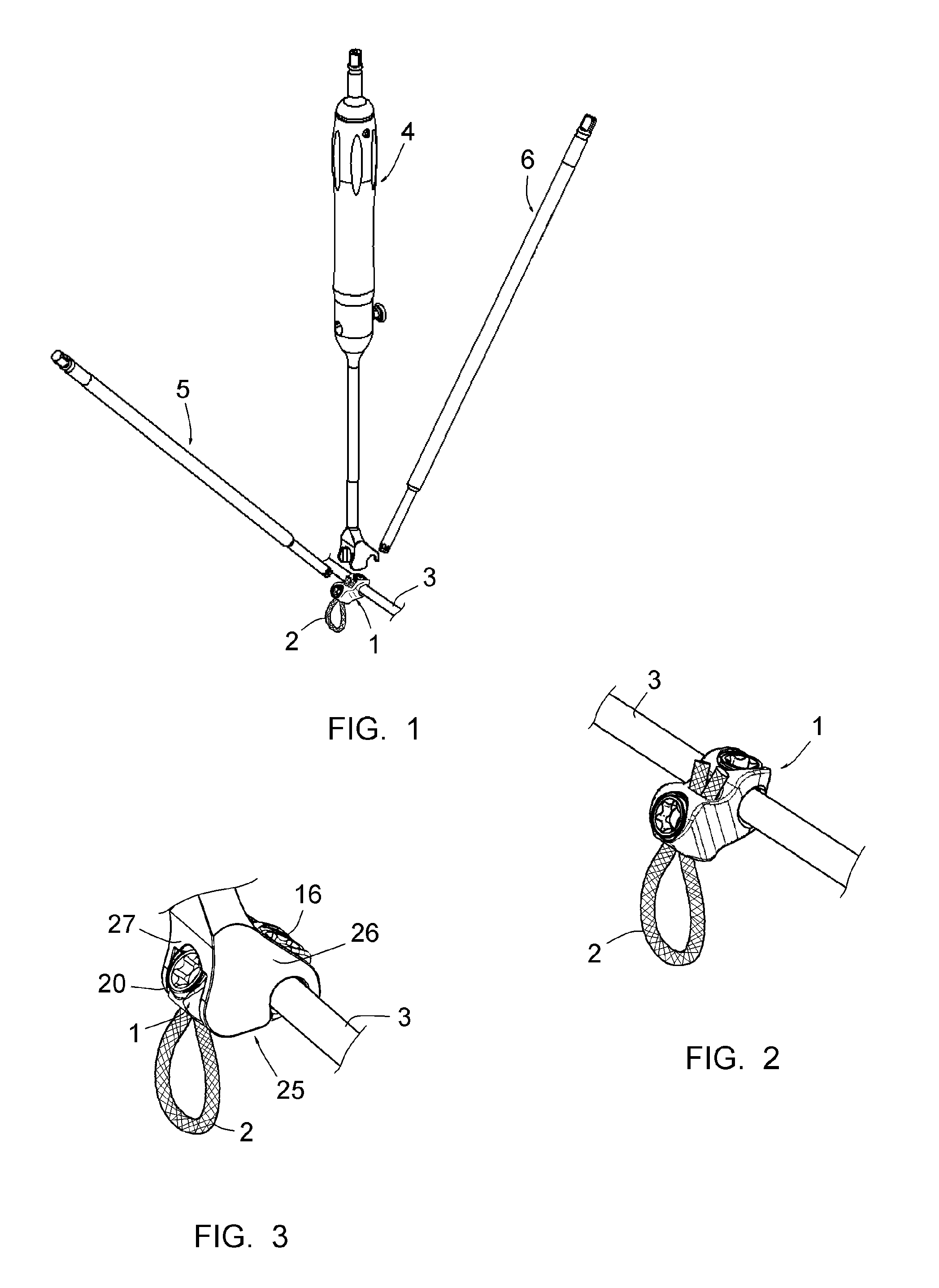
[0063]FIG. 1 shows a connector 1, a ligament 2, a portion of a connecting bar 3, a lever 4 and two maneuvering instruments 5, 6 of a piece of vertebral osteosynthesis equipment. This equipment also includes anchor members for anchoring the bar 3 to the vertebrae, in particular pedicle screws and / or lamina hooks (not shown). It includes a plurality of connectors 1, ligaments 2, and levers 4, making it possible to treat a plurality of vertebrate simultaneously, as well as a second connecting bar and other anchor members for anchoring said second part of the vertebrae, making it possible to anchor said second bar on the sides of the vertebrae opposite that on which the bar 3 is installed.

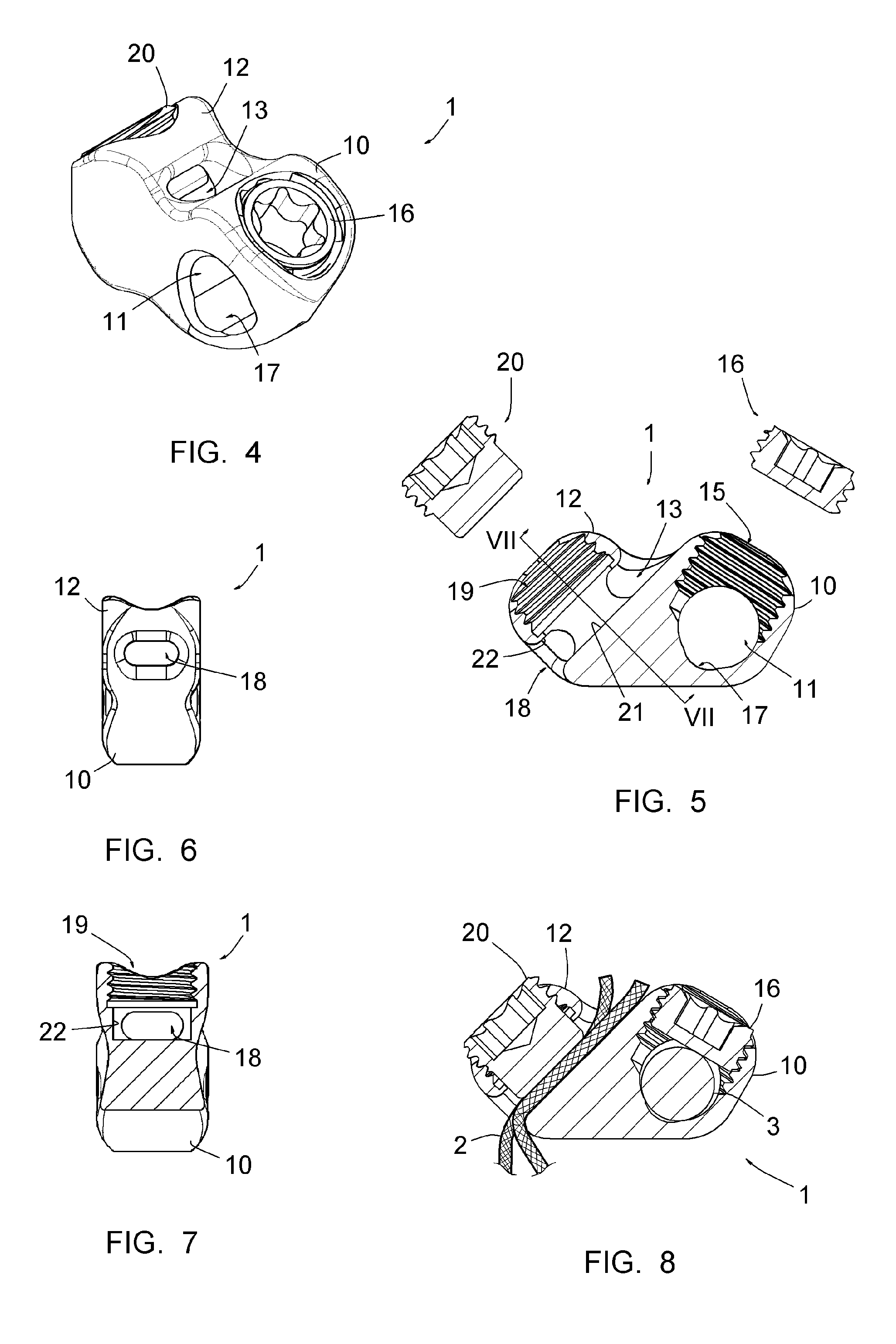
[0064]FIGS. 4 to 6 show that the connector 1 includes a first portion 10, in which a first conduit 11 is formed for engaging on the bar 3, and a second portion 12 in which a second conduit 13, for receiving the two strands of the ligament 2, is formed, side-by-side.

[0065]The first conduit 11 communicat...


PUM


Abstract

The equipment includes at least one connecting bar, at least one flexible ligament, and at least one connector making it possible to connect the ligament to the connecting bar. The connector having a first conduit for engaging the connecting bar, equipped with a device for immobilizing the connector relative to the connecting bar, and a second conduit for receiving at least one strand of the ligament, having an insertion opening for this or these strands and an outlet opening for this or these strands, and equipped with devices for mobilizing the ligament relative to the connector. The second conduit is rectilinear between the insertion opening of the strand(s) of the ligament and the outlet opening. The second conduit has a transverse section adjusted to the transverse section of the strand(s) of the ligament that it is intended to receive, i.e. a transverse section just sufficient to allow sliding of the strand(s) of the ligament in the second conduit, but such that the strand(s) are in close contact with the walls delimiting the second conduit.

Description

CROSS REFERENCE TO RELATED APPLICATION[0001]This application is a national stage entry of PCT / IB2012 / 052985 filed Jun. 13, 2012, under the International Convention claiming priority over French Application No. 1155504 filed Jun. 22, 2011.FIELD OF THE INVENTION[0002]The present invention relates to vertebral osteosynthesis equipment.BACKGROUND OF THE INVENTION[0003]To straighten a distracted spine, in particular in the case of scoliosis, it is well known to use vertebral osteosynthesis equipment including anchoring members for anchoring to the vertebrate (pedicle screws and / or lamina hooks), connecting bars, and connectors for connecting said bars to said anchoring members.[0004]This type of equipment assumes that pedicles that are slightly or not at all deteriorated exist for anchoring screws, or that there are sufficient spaces at the laminas to engage the hooks behind said laminas. This type of equipment is therefore not suitable when the pedicles of the vertebrae are deteriorated...

Claims


Application Information

Patent Timeline
Patent Type & Authority Patents(United States)
IPC IPC(8): A61B17/70A61B17/84
CPCA61B17/7053A61B17/7001A61B17/7076A61B17/7082A61B17/842
Inventor CLEMENT, JEAN-LUCAMINIAN, AFSHIN
Owner MEDICREA INT SA
Why Eureka
Try Eureka