
Asymmetrical surgical wrist rest

a wrist rest and asymmetric technology, applied in the field of asymmetric surgical wrist rests, can solve the problems of surgeons having to adopt uncomfortable and unsuitable wrist and hand positions, and either eye of patients is off center

Active Publication Date: 2016-04-19
WOLF BENJAMIN +3
View PDF15 Cites 3 Cited by
  • Summary
  • Abstract
  • Description
  • Claims
  • Application Information

AI Technical Summary

Benefits of technology

This patent is about support devices that are designed to be asymmetric or angled, which makes it easier to work on non-centered parts of objects. The support devices help operators comfortably rest their hand while directing procedures towards the non-centered parts of the work objects. The technical effect is improved access and comfort for operators while working on non-centered parts of objects.

Problems solved by technology

In the case of eye surgery, this design presents a recurring problem in that either eye of the patient is off-center within the symmetric wrist rest.
Regardless of which eye is being subject to surgery, the surgeon must often adopt uncomfortable and unsuitable wrist and hand positions to accomplish a given surgical maneuver.

Method used


Image

  • Asymmetrical surgical wrist rest
  • Asymmetrical surgical wrist rest
  • Asymmetrical surgical wrist rest

Examples


Embodiment Construction

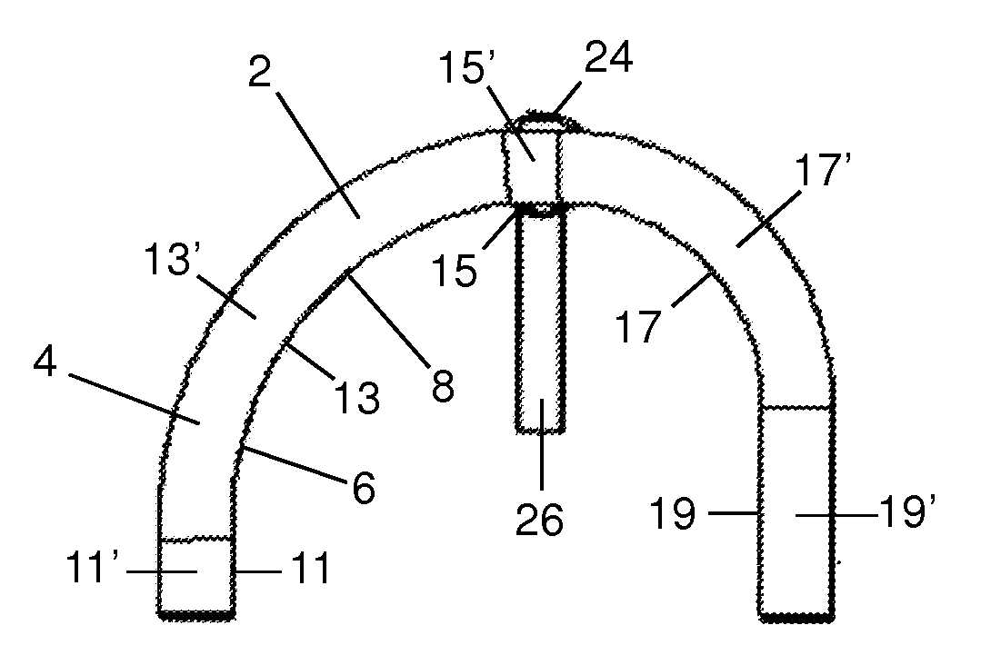
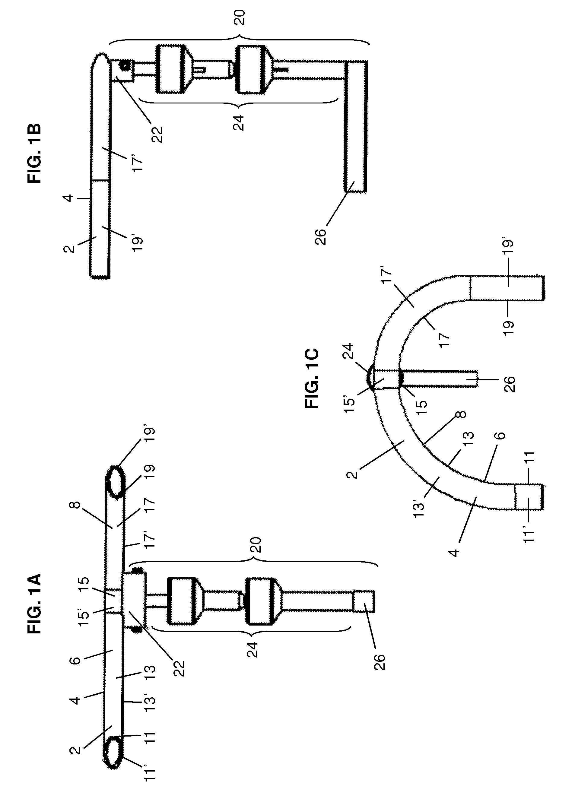
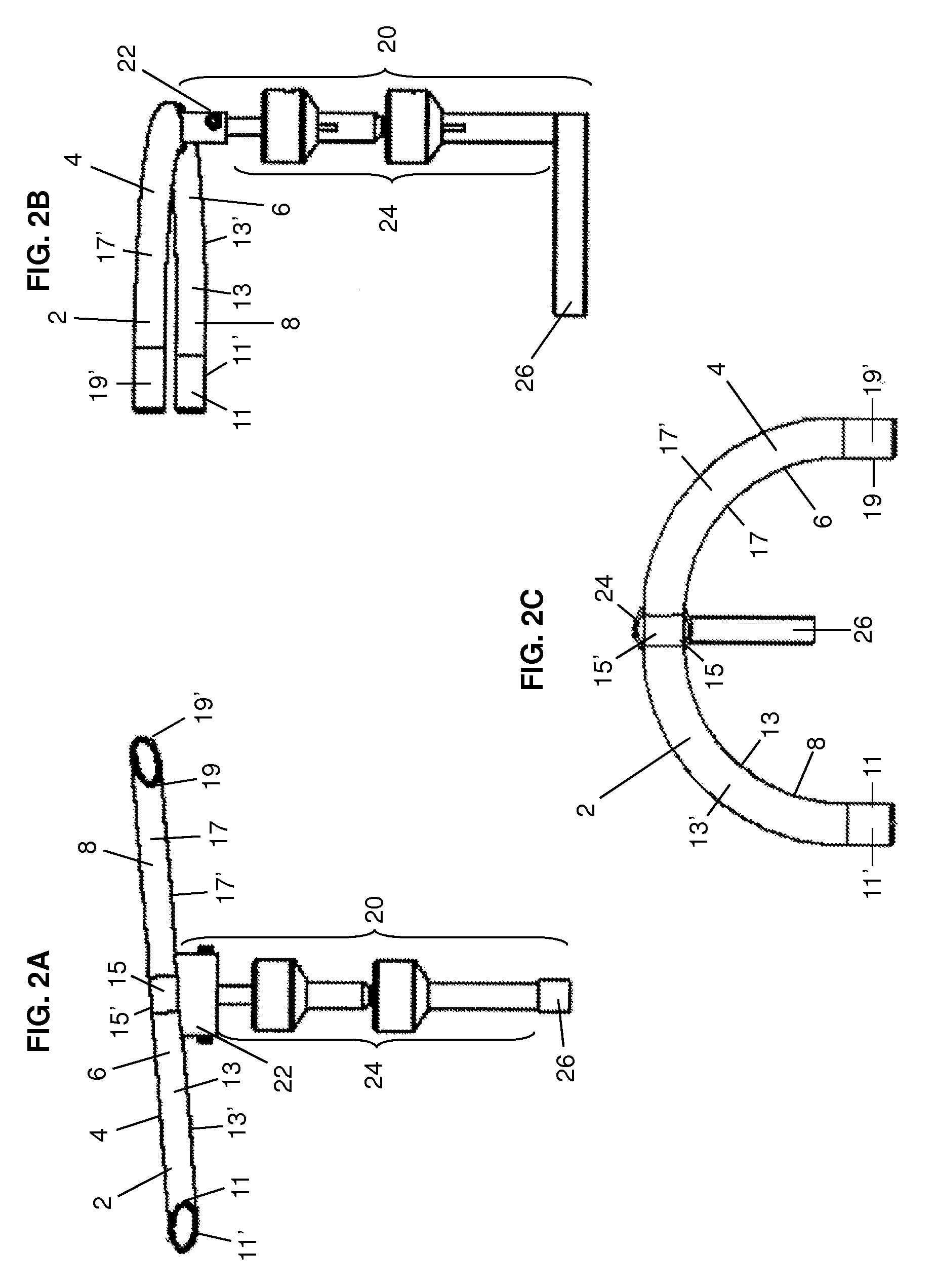
[0024]The support devices of the present invention include a support member 2, as shown in FIGS. 1A-3C. The term “support member” refers to any physical or extended object suitable for supporting a hand, arm, or wrist thereon. The support member 2 includes a top surface 4 and a front surface 6. The top surface 4 serves as an area of contact for the hand, arm, or wrist on the support member 2. Depending on the particular use, the top surface 4 may be flat, curved, angled, or contoured, and any angles, curvature, or contours may have consistent degrees of curvature or varying degrees of curvature. The front surface 6 defines a limit of extension of the top surface 4 and therefore defines a limiting boundary of the latter. As shown in the exemplary versions of the invention, the front surface 6 is substantially orthogonal or comprises at least a portion that is substantially orthogonal to the top surface 4.

[0025]In the exemplary versions of the invention shown in FIGS. 1A-3C, the suppo...


PUM


Abstract

Wrist, hand, or arm support devices are provided. The support devices include a support member having a top surface and a front surface. The top surface is oriented at either a parallel angle or a non-parallel angle with respect to a work surface. The front surface curves upon itself to form either a symmetric or an asymmetric arc. Preferred versions of the support devices described herein include at least one of a top surface oriented at a non-parallel angle with respect to the work surface or a front surface that curves upon itself to define an asymmetric arc. Mounting members for connecting the support member to an operating surface are also provided. The support devices described herein permit an operator to comfortably rest his or her hand on the support devices while directing procedures toward non-centered portions of work objects.

Description

CROSS-REFERENCE TO RELATED APPLICATIONS[0001]This application claims priority under 35 USC §119(e) to U.S. Provisional Patent Application 61 / 405,996 filed Oct. 22, 2010, the entirety of which is incorporated herein by reference.FIELD OF THE INVENTION[0002]The invention is directed to devices for supporting an operator's hand, arm, or wrist while performing fine-tuned, delicate movements about a work object, such as performing surgery or similar operations on a head, neck, or eye of a patient.BACKGROUND[0003]When a physician performs eye surgery and similar delicate operations, it is important that the hand holding the scalpel or other instrument has a firm support throughout the operating procedure to permit small and precise movements. Various devices for supporting a surgeon's hand include support tables, arm rests, and wrist rests. See, e.g., U.S. Pat. Nos. 4,378,108; 4,018,217; and U.S. Design Pat. No. 264,875. Such devices are widely used in ophthalmic surgery, otolaryngology s...

Claims


Application Information

Patent Timeline
Patent Type & Authority Patents(United States)
IPC IPC(8): A61G13/12
CPCA61B90/60
Inventor WOLF, BENJAMINWOLF, JACOBWOLF, MITCHELLWOLF, STEPHANIE
Owner WOLF BENJAMIN
Learn More