Fixed platen of injection molding machine

a technology of injection molding machine and plate, which is applied in the field of fixed plate, can solve the problems of mold deformation, mold damage, and burr in the molded article, and achieve the effect of preventing unbalanced load from being applied, improving the surface pressure distribution of mold parts, and reducing the amount of molded parts

Active Publication Date: 2016-04-19
FANUC LTD
View PDF24 Cites 7 Cited by
  • Summary
  • Abstract
  • Description
  • Claims
  • Application Information

AI Technical Summary

Benefits of technology

[0016]Thus, an object of the invention is to provide a fixed platen that improves a surface pressure distribution of a mold parting surface without increasing the weight of the platen, and prevents the unbalanced load from being applied to the tie bar.
[0020]According to the invention, it is possible to provide a fixed platen that improves the surface pressure distribution of the mold parting surface without increasing the weight of the platen and to prevent the unbalanced load from being applied to the tie bar.

Problems solved by technology

Therefore, force escapes from the central portion of the mold and a contact surface pressure is lowered, and thus, there is concern that burr occurs in a molded article.
Furthermore, on the contrary, when the excessive pressure locally acts on the mold, there is also concern that the mold may be deformed, or the mold itself may be damaged.
In order to reduce a difference in pressure depending on locations of a platen, it is effective to improve rigidity of the platen, but in a method of simply increasing a thickness of the platen, the platen weight increases, which leads to increased costs.
However, in the above-described technique, in case where a notch is provided over the entire circumference by increasing a notch portion, in some cases, an outer circumferential portion of mold mounting portion cannot fully support the mold clamping force, as a result, the outer circumferential portion of a mold mounting portion may be deformed in the opposite direction such that the outer circumferential portion of the mold may open.
In addition, in some cases, due to an increase in deformation of a tie bar fixing portion, the tie bar is bended, and thus, failures such as break of the tie bar may occur.
However, since the extension portion is provided only in the vertical direction, in some cases, the adjustment of other directions cannot be performed well.

Method used


Image

  • Fixed platen of injection molding machine
  • Fixed platen of injection molding machine
  • Fixed platen of injection molding machine

Examples


first embodiment

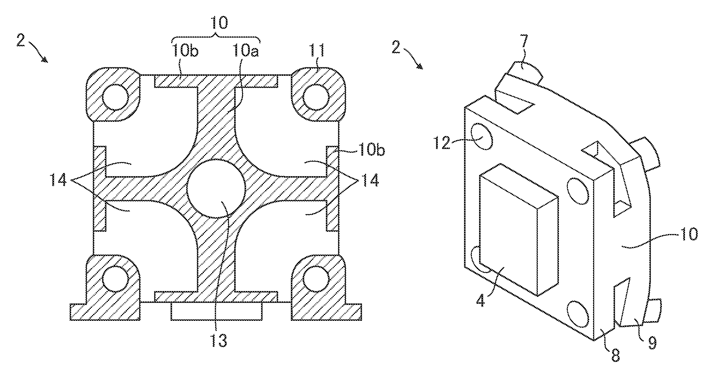
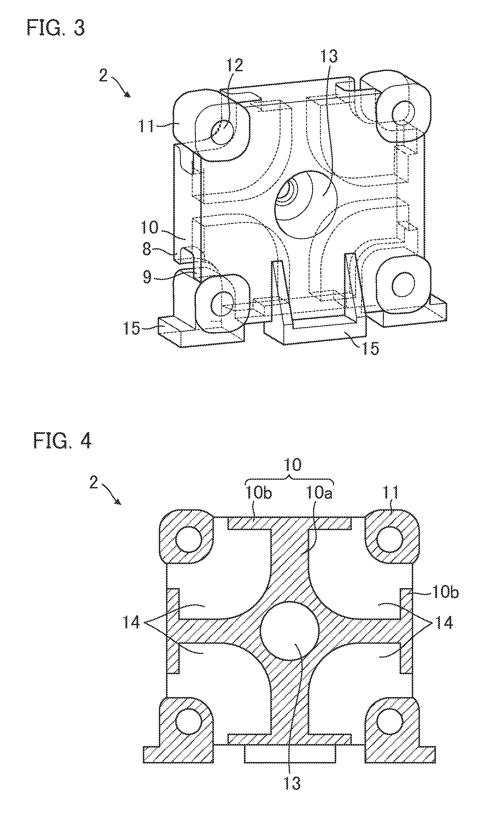
[0032]First, the fixed platen according to the invention will be described with reference to FIGS. 1 to 6.

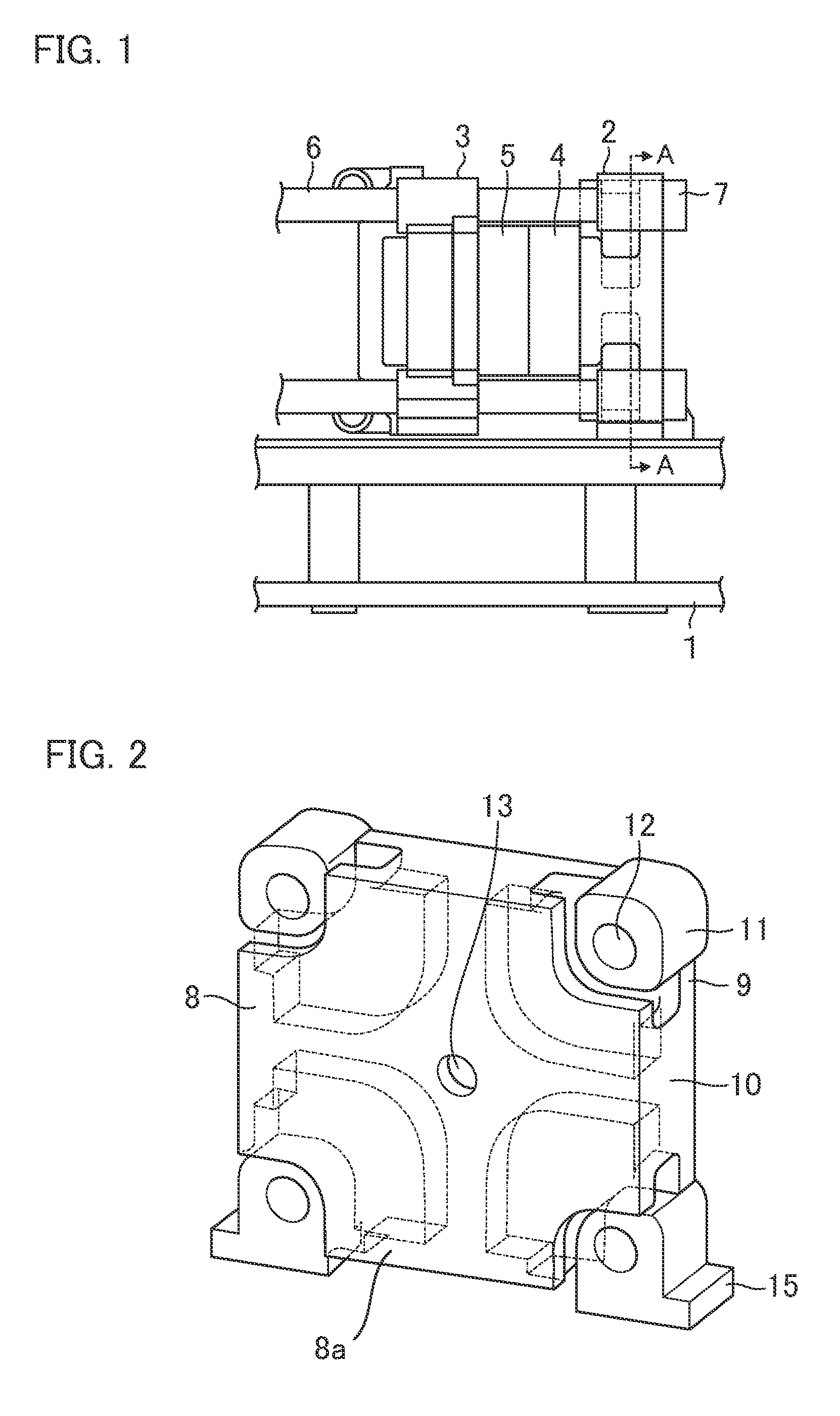
[0033]FIG. 1 is a diagram illustrating a mold clamping mechanism of an injection molding machine that uses a first embodiment of the fixed platen according to the invention.

[0034]The mold clamping mechanism is equipped with a fixed platen 2 fixed to a base frame 1, and a movable platen 3 which is movably disposed while maintaining a state in which a mold surface (a surface of a fixed-side mold 4 and a surface of a movable-side mold 5 to be described below) is parallel to the fixed platen 2. A rear platen (not illustrated) is provided on a side of the movable platen 3 opposite to the fixed platen 2, at a position spaced apart from the movable platen 3. Furthermore, tie bars 6 are provided between the fixed platen 2 and the rear platen, and a tie bar nut 7 is screw-engaged with an end portion of each of the tie bars 6 penetrating through the fixed platen 2. Furthermore, the fixed-...

second embodiment

[0048]Next, the fixed platen according to the present invention will be described with reference to FIG. 7.

[0049]In this embodiment, as illustrated in FIG. 7, the cross-shaped connecting portion 10a of the load transmitting portion 10 is configured to narrow as it approaches the outer circumferential portion. In particular, when a mold to be mounted on the fixed platen 2 becomes larger, the rigidity of the mold becomes higher, and the deformation of the fixed platen 2 decreases. Accordingly, even if the width of the cross-shaped connecting portion 10a near the outer circumferential portion is narrow, it is possible to support the load.

third embodiment

[0050]Next, the fixed platen according to the invention will be described with reference to FIG. 8.

[0051]In this embodiment, as illustrated in FIG. 8, a through hole 16a is formed in the extension connecting portion 10b of the load transmitting portion 10, and another through hole 16b is formed in the tie bar support portion 9. Since a cored opening 14 is provided on the inner side of the tie bar support portion 9, it is difficult to remove sand remaining therein at the time of casting production.

[0052]In this embodiment, by forming the through holes 16a and 16b in the extension connecting portion 10b of the load transmitting portion 10 and the tie bar support portion 9, respectively, internal sand generated during the casting production is easily removed through the through holes 16a and 16b. In this embodiment, although the through holes 16a and 16b are provided in the extension connecting portion 10b of the load transmitting portion 10 and the tie bar support portion 9, as long a...


PUM

PropertyMeasurementUnit
pressureaaaaaaaaaa
clamping forceaaaaaaaaaa
contact surface pressureaaaaaaaaaa

Abstract

A fixed platen of an injection molding machine is constituted by a mold mounting portion, a tie bar support portion disposed to be spaced apart from the mold mounting portion, and a load transmitting portion that connects the mold mounting portion with the tie bar support portion. Furthermore, the load transmitting portion is constituted by a cross-shaped connecting portion, and an extension connecting portion that extends along the outer circumferential portion of the mold mounting portion.

Description

RELATED APPLICATIONS[0001]The present application claims priority to Japanese Application Number 2014-023679, filed Feb. 10, 2014, the disclosure of which is hereby incorporated by reference herein in its entirety.BACKGROUND OF THE INVENTION[0002]1. Field of the Invention[0003]The present invention relates to a fixed platen used in an injection molding machine.[0004]2. Description of the Related Art[0005]A mold clamping mechanism of an injection molding machine is equipped with a fixed platen fixed to a base frame, and a movable platen disposed to be movable with respect to the fixed platen, while maintaining a posture that is parallel to the fixed platen. Furthermore, a fixed-side mold is mounted to the fixed platen, and a movable-side mold is mounted to the movable platen. These molds are opened and closed, and clamped by moving the movable platen forward and backward with respect to the fixed platen.[0006]The mold clamping mechanism is required to reliably clamp the fixed platen ...

Claims


Application Information

Patent Timeline
Patent Type & Authority Patents(United States)
IPC IPC(8): B29C45/17
CPCB29C45/1744
Inventor SENGA, MASATOSHI
Owner FANUC LTD
Why Eureka
Try Eureka