Oven having a rotating door

a technology of rotating doors and ovens, which is applied in the field of ovens, can solve the problems of tremendous heat loss, conveyor ovens also have disadvantages, and limit the number of substantially identical food items placed in the ovens,

Active Publication Date: 2016-05-03
OVENTION
View PDF48 Cites 13 Cited by
  • Summary
  • Abstract
  • Description
  • Claims
  • Application Information

AI Technical Summary

Benefits of technology

[0016]More particularly, the present invention relates to an oven comprising a housing, a cavity located within the housing, a rotator comprising a first food loading section and a second food loading section, and a heat source for providing heat to the cavity. The cavity includes a single opening for loading a food item into the cavity. When one of the first food loading section and the second food loading section is located outside of said cavity, the other of the first food loading section and the second food loading section is located within said cavity. A first cook setting of the oven when the first food loading section is within the cavity and a second cook setting of the oven when the second food loading section is within the cavity are independently controllable. The first food loading section and the second food loading section may be separated by a divider, which prevents heat from escaping from the cavity through the opening. The divider may be removable. The oven may further comprise a motor for rotating the rotator.

Problems solved by technology

The only limit to how many substantially identical food items may be placed in the conveyor oven is the speed of the conveyor belt, which correlates to the residence time inside the heated cavity for food items to be sufficiently cooked.
However, conveyor ovens also have their disadvantages.
Conveyor ovens are very efficient when cooking similar food items, but not for cooking a variety of food items that require vastly different cooking times and heat transfer profiles.
In addition, the two openings contribute to tremendous heat loss during the operation of conveyor ovens.
The lost heat must be replaced in order to maintain cook temperature, and as a result conveyer ovens are not energy efficient.
Furthermore, the space required by the loading and unloading platforms of conveyor ovens limit the application of conveyor ovens to relatively large commercial kitchens.

Method used


Image

  • Oven having a rotating door
  • Oven having a rotating door
  • Oven having a rotating door

Examples


Embodiment Construction

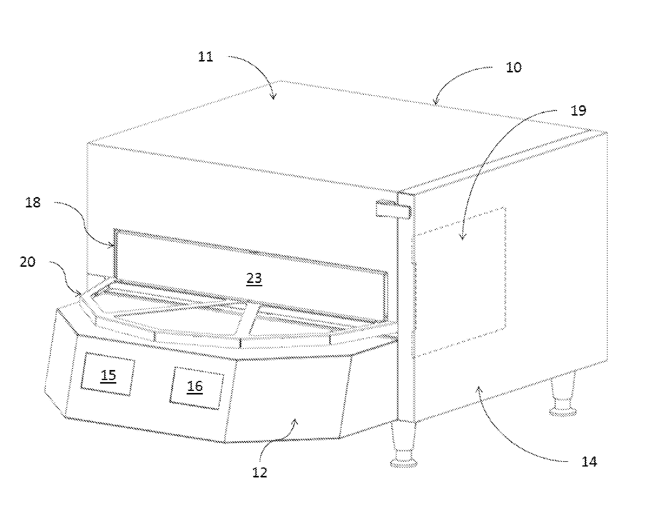
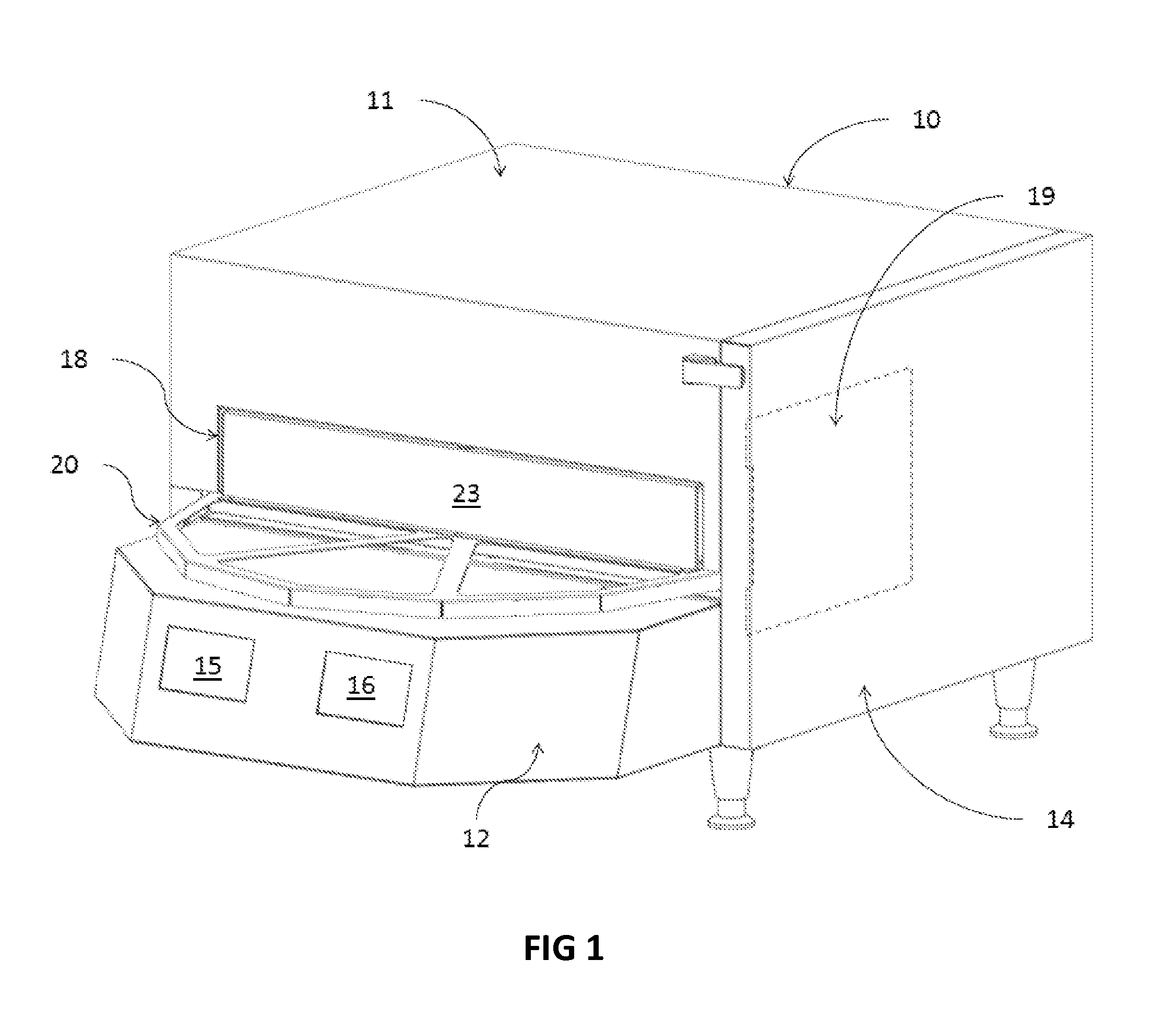
[0019]Referring now to the drawings and in particular to FIG. 1, there is depicted an isometric view of an oven, in accordance with a preferred embodiment of the present invention. As shown, an oven 10 includes a housing 11 and a base 12. Housing 11 includes a single front opening 18 for loading a food item into the oven. In addition, the housing 11 may also include a side opening 19 for maintenance purposes. During cooking operations, front opening 18 can be covered by a divider 23 located on a rotator 20, and side opening 19 can be covered by a side door 14.

[0020]Base 12 includes a first control panel 15 and a second control panel 16. First and second control panels 15, 16 may be implemented with touchscreens. They can also be implemented with keypads, liquid crystal displays (LCDs), and / or other means for entering cook settings. An operator can enter commands and / or cook setting parameters, such as cooking temperature, cooking time, blower speed, etc., via first and second contro...


PUM


Abstract

An oven comprising a housing, a cavity located within the housing, and a rotator having a first food loading section and a second food loading section is disclosed. The cavity includes a single opening for loading a food item into the cavity. If one of the first food loading section and the second food loading section is located outside of said cavity, then the other of the first food loading section and the second food loading section is located within said cavity. A first cook setting of the oven when the first food loading section is within the cavity and a second cook setting of the oven when the second food loading section is within the cavity are independently controllable. The first food loading section and the second food loading section may be separated by a divider, which prevents heat from escaping from the cavity through the opening.

Description

CROSS REFERENCE TO RELATED APPLICATIONS[0001]This application is a continuation-in-part of U.S. application Ser. No. 13 / 077,143, filed on Mar. 31, 2011, a continuation-in-part of U.S. application Ser. No. 13 / 236,695, filed on Sep. 20, 2011, and a continuation-in-part of U.S. application Ser. No. 13 / 774,617, filed on Feb. 22, 2013, the entire contents of each of which are incorporated herein by reference.FIELD OF INVENTION[0002]The present invention relates to ovens in general, and in particular to an oven having a rotating door, wherein the oven is capable of providing continuous food cooking while minimizing heat loss.BACKGROUND OF THE INVENTION[0003]A conveyor oven typically has a first opening through which uncooked food enters and a second opening at the opposite end of the oven through which cooked food exits. A stainless steel conveyor belt is commonly used to carry food items from a loading platform through a heated cavity between the first and second openings and ultimately ...

Claims


Application Information

Patent Timeline
Patent Type & Authority Patents(United States)
IPC IPC(8): A47J37/04A21B3/07A21B1/42A47J37/06F24C15/32A21B1/24A21B1/26A21B1/44
CPCA47J37/049A21B1/245A21B1/26A21B1/42A21B1/44A21B3/07A47J37/067F24C15/322
Inventor MCKEE, PHILIP R.JOHNSON, ALEX WAYNE
Owner OVENTION
Why Eureka
Try Eureka