Soil anchor footing

a technology of soil anchors and footings, which is applied in the field of soil anchor footings, can solve the problems of large volume of concrete, large excavation, and more soil disposal, and achieve the effects of easy construction, low weight, and low cos

Inactive Publication Date: 2016-05-03
ARYA ANOOP KUMAR
View PDF35 Cites 7 Cited by
  • Summary
  • Abstract
  • Description
  • Claims
  • Application Information

AI Technical Summary

Benefits of technology

[0019]Briefly, in accordance with the principles and teachings of the present invention, the soil anchor footing comprises the use of steel deformed bars which act as mini piles. Having deformed surfaces, the bars have high soil adhesion, hence, more uplift and downward force resistance capacity. The bars are closely spaced, 100 mm to 300 mm center-to-center spacing therebetween, so that the footing requires a smaller space. Since the bars are pushed into the ground, very small excavations are required to accommodate the same, only the footing top slab being required, thereby resulting in less soil disposal. The footing can also be of the pre-cast type, wherein the whole footing can be installed within the ground by pile driving equipment or a mobile press, making the construction work very fast and simple.
[0021]This footing is light in weight, economical to produce, environmentally friendly, easy to construct, saves time in both manufacture and installation, and requires less space as compared to conventional pad type footings.

Problems solved by technology

Hence, it requires large volumes of concrete, more space, more excavation, and more soil disposal.
Though the aforenoted conventional and similar systems have been designed to provide certain advantages, they also suffer from various shortcomings.
Both of the anchors disclosed within these prior art patents, however, are expensive and need special machinery to install.
It appears that this foundation pier has limitations as to its applications and can be used only for small loads.
Hence, this device again has limited use.
This system has the inherent disadvantage of being cumbersome and expensive.

Method used


Image

  • Soil anchor footing
  • Soil anchor footing
  • Soil anchor footing

Examples


Embodiment Construction

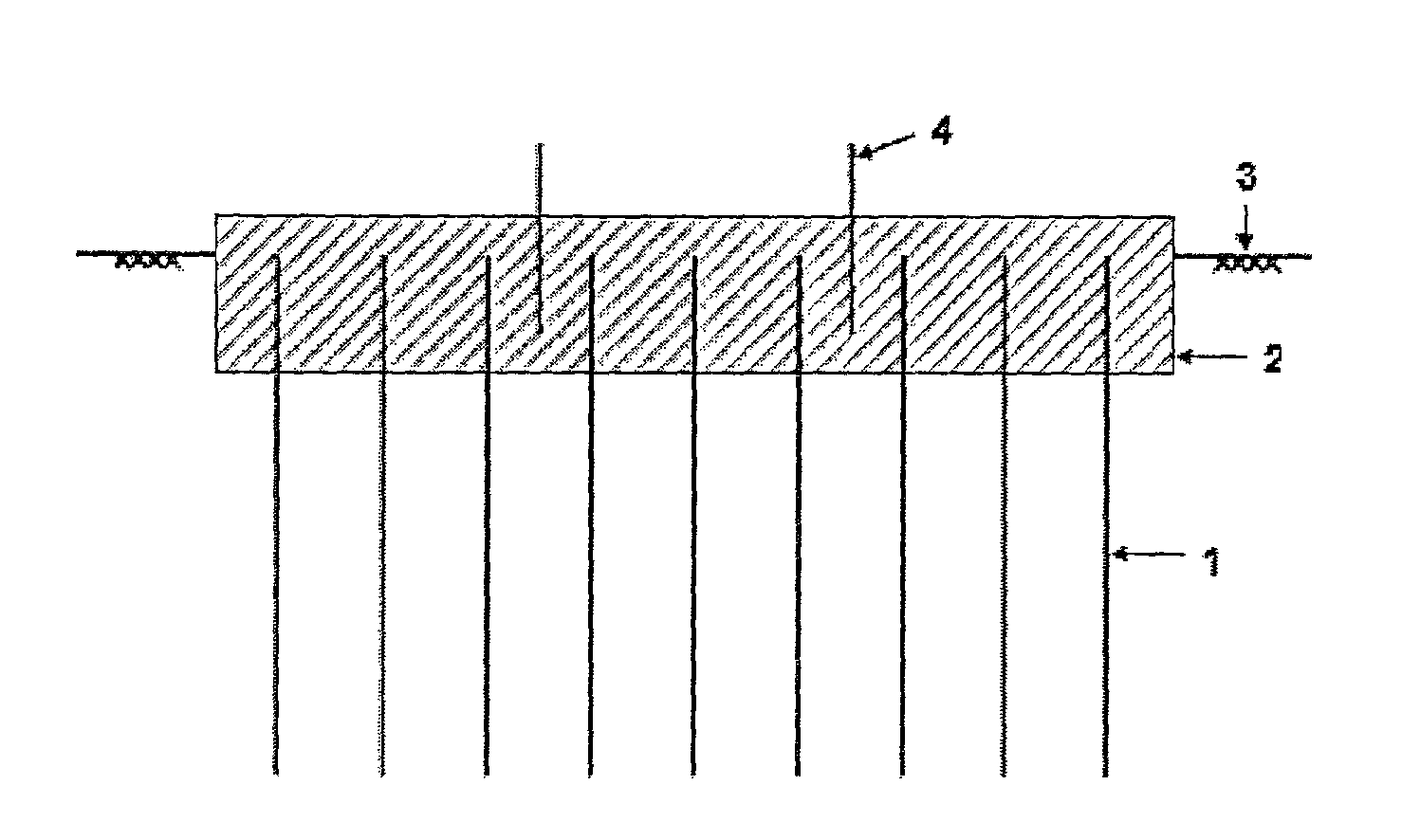
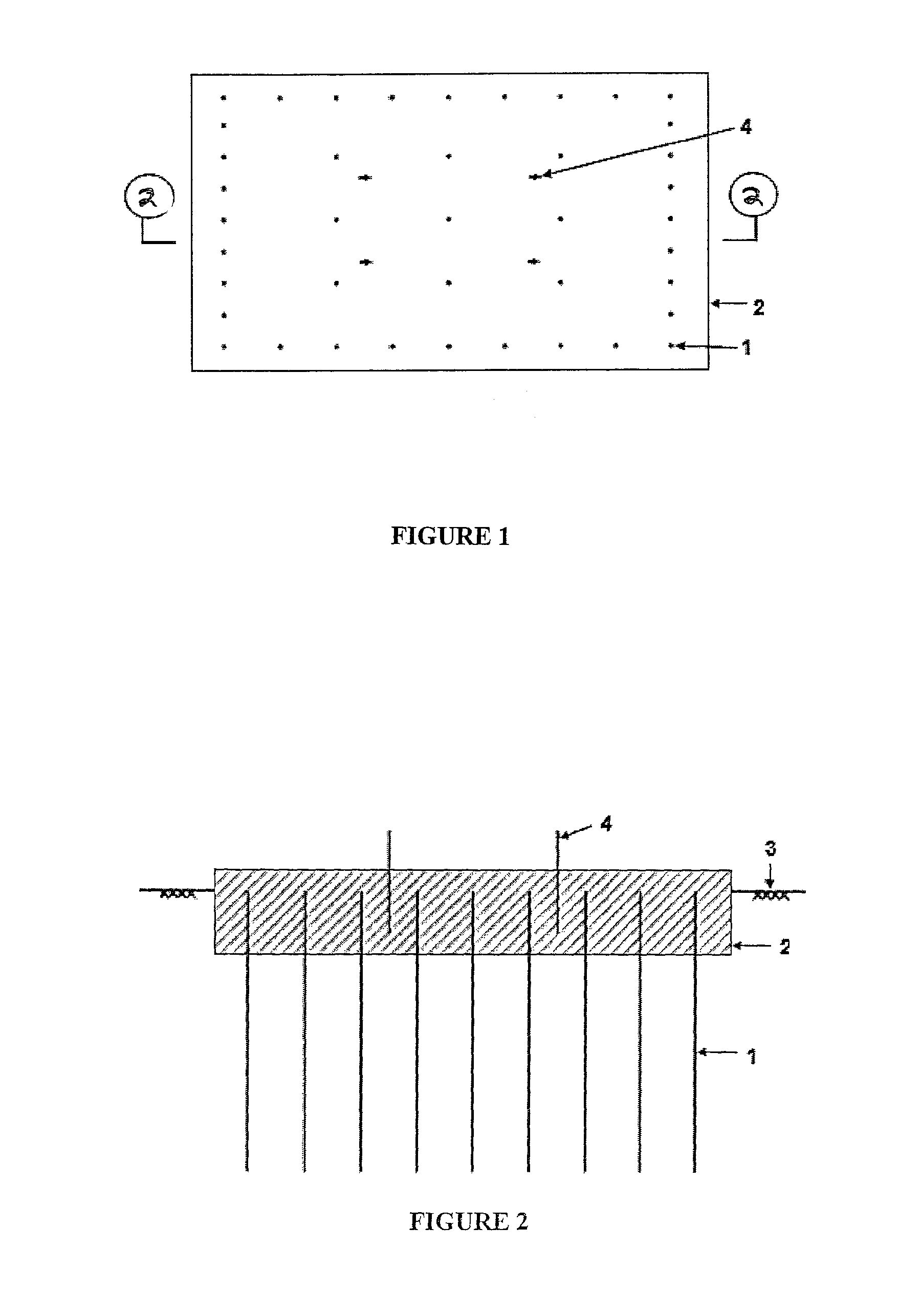
[0035]In connection with a first embodiment of a soil anchoring footing as constructed in accordance with the principles and teachings of the present invention, the first embodiment soil anchoring footing is illustrated in FIGS. 1 and 2. This type of footing can be constructed in two ways—as a cast-in-situ type, and as a pre-cast type. In connection with the cast-in-situ type, the ground is first excavated for the top slab, 150 mm to 350 mm deep, depending upon the thickness of the slab. After this, about 0.3 m to 2 m long deformed steel or fiber reinforced polymer (FRP) anchor bars 1, 12 mm to 36 mm diameter, are pushed individually into the ground 3 by means of an industrial hammer, or in groups, using pile driving equipment or a mobile press, leaving approximately 150 mm to 350 mm of the upper portions of the anchor bars 1 exposed above ground. As the anchor bars 1 have deformed surfaces, and as they are pushed into the ground 3, they exhibit good soil anchorage capacity resultin...


PUM


Abstract

The present invitation relates to a soil anchor footing supporting system within the ground surface to support steel or concrete column, brick or block wall, light post, sign post, substation equipment, pre-cast panel, retaining wall etc. It comprises of a footing slab (2) made of concrete; plurality of deformed steel bars (1) or fiber reinforced polymer (FRP) bars embedded in the lower surface of the concrete slab (2) and plurality of anchor bolts (4) or reinforcing starter bars which are embedded into upper surface of concrete slab (2) to suit steel or concrete column. The bars, which act as mini piles, are configured for ground penetration and a concrete slab is cast on top to encase all the bars and is capable of holding desired loads. These footings can be cast-in-situ type where the bars are pushed into ground (3) individually or in groups and concrete is cast on top, or it can be pre-cast type where, the whole footing is pushed into ground using pile driving equipment or mobile press.

Description

CROSS REFERENCE TO RELATED PATENT APPLICATIONS[0001]This patent application is related to, and based upon, Australian Provisional Patent Application Number SPEP-15863657 filed Jan. 31, 2012, and Indian Patent Application 3599 / CHE / 2012 A filed on Aug. 31, 2012, both applications of which are incorporated by reference herein and the priority benefits of which are hereby claimed.FIELD OF THE INVENTION[0002]The present invitation relates to a soil anchor footing, and more particularly for a foundation supporting system within the ground surface for columns, walls, light posts, sign posts, electrical substation equipment, railway infrastructure, light industrial structures, or the like, and a method for making the same.BACKGROUND OF THE INVENTION[0003]The advent of technology has led to a sea change in the civil engineering construction industry. Foundation support systems for the columns of buildings are characterized by suitable footings based upon the soil condition. A footing is basi...

Claims


Application Information

Patent Timeline
Patent Type & Authority Patents(United States)
IPC IPC(8): E02D27/50E02D27/42E02D5/18
CPCE02D5/18E02D27/42E02D27/50E02D2600/30
Inventor ARYA, ANOOP KUMAR
Owner ARYA ANOOP KUMAR
Why Eureka
Try Eureka