Angular velocity sensor

a technology of angular velocity and sensor, applied in the direction of acceleration measurement using interia force, instruments, devices using electric/magnetic means, etc., can solve the problems of unstable movement state of rails and decrease the detection accuracy of angular velocity, and achieve the effect of suppressing the decline of angular velocity detection accuracy

Active Publication Date: 2016-05-03
DENSO CORP
View PDF32 Cites 2 Cited by
  • Summary
  • Abstract
  • Description
  • Claims
  • Application Information

AI Technical Summary

Benefits of technology

[0006]It is an object to provide an angular velocity sensor that suppresses a decline of a detection accuracy in angular velocity.

Problems solved by technology

As a result, the movement state of the rails become unstable, involving a defect to decrease the detection accuracy in angular velocity.

Method used


Image

  • Angular velocity sensor
  • Angular velocity sensor
  • Angular velocity sensor

Examples


first embodiment

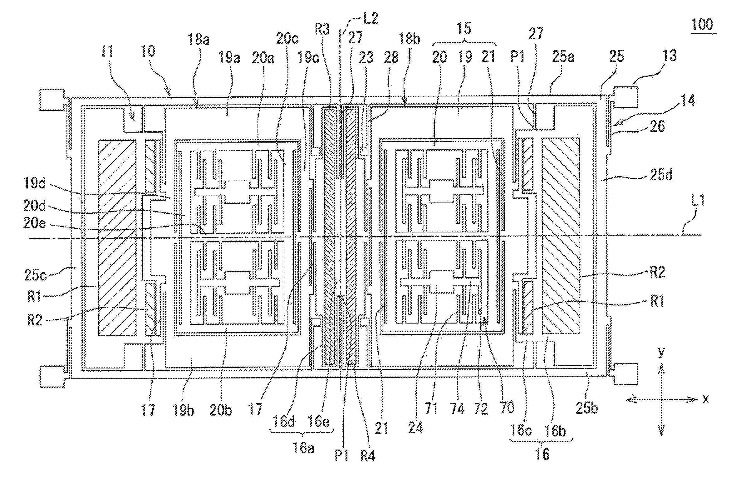
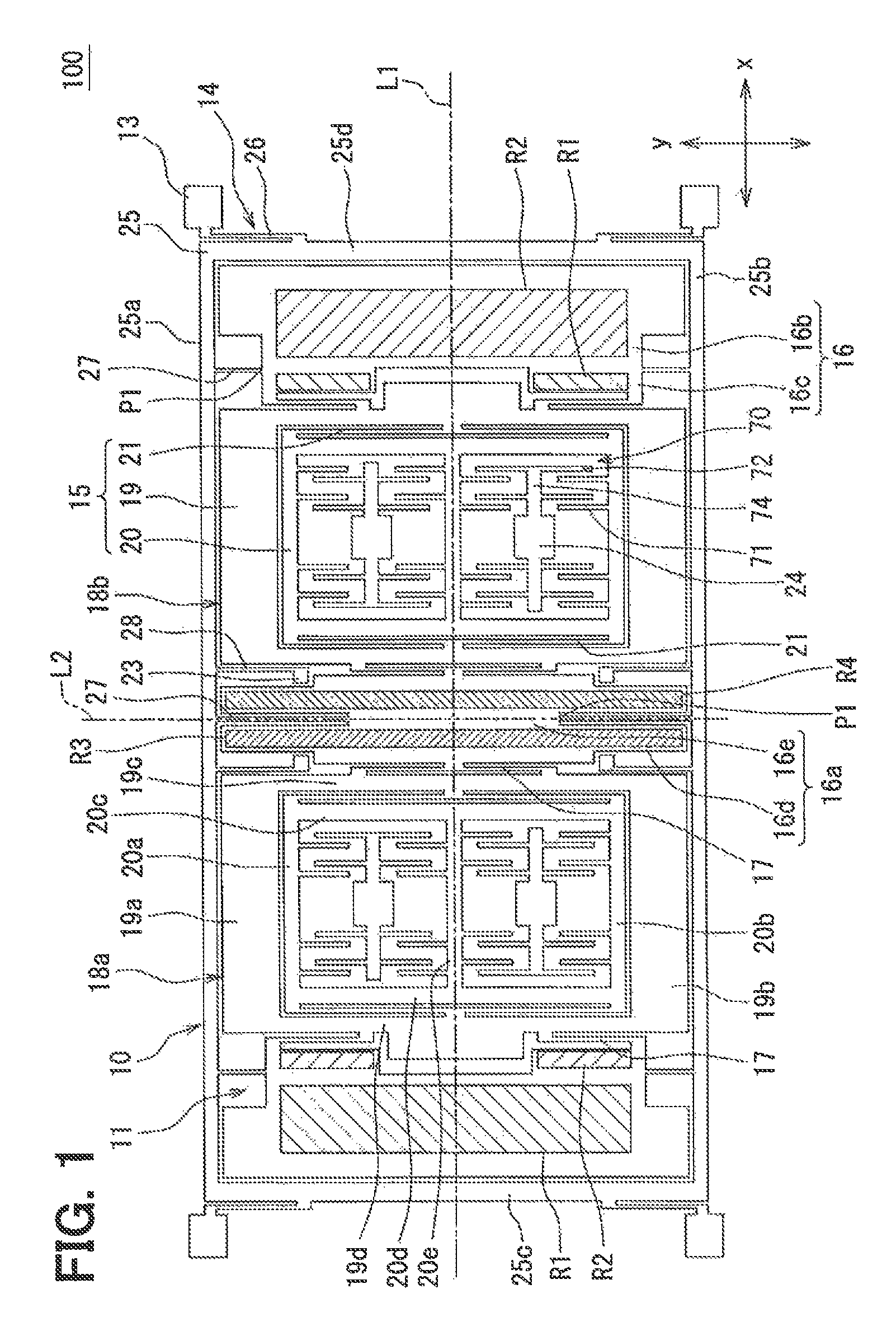
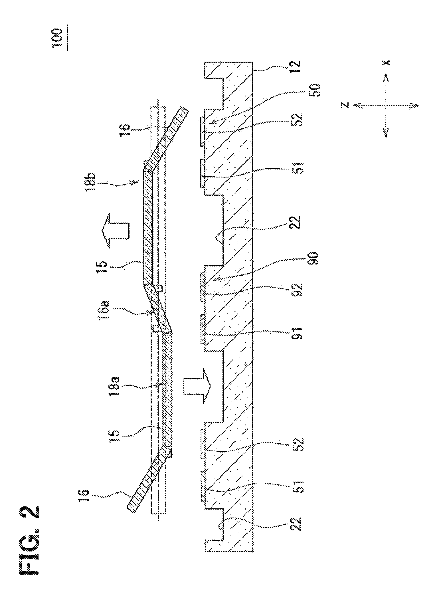
[0022]The following will explain an angular velocity sensor according to a first embodiment with reference to FIGS. 1 to 7. FIG. 1 provides hatching to facing ranges R1 to R4 (mentioned later) of a vibrator 11; the facing ranges R1 to R4 face electrodes 51, 52, 91, 92. FIG. 2 illustrates a sectional view of the vibrator 11 along a penetrating direction L1 illustrated in FIG. 1, while illustrating an immovable state of the vibrator 11 using a range surrounded by broken lines. FIG. 4 to FIG. 7 omit components unnecessary for explaining a moving state of the vibrator 11 to illustrate schematically. Schematic illustration contains the components overlapping, which should not be overlapping actually. FIG. 4 to FIG. 7 are obtained from a simulation, and a little different from the configuration in FIG. 1 to FIG. 3; however, they have the same configuration in a fundamental portion (featured portion of the present disclosure).

[0023]The following defines three axes of x axis, y axis, and z ...


PUM


Abstract

An angular velocity sensor includes a vibrator located along x-y plane specified by x direction and y direction that are orthogonal to each other; a substrate that is separated away from the vibrator along z direction perpendicular to the x-y plane; an anchor device extended from the substrate to the x-y plane in which the vibrator is located; a linkage beam device that links the anchor device to the vibrator, the linkage beam being able to twist about the y direction; an excitation portion that vibrates the vibrator along the z direction; and a detection portion that detects an angular velocity based on a displacement along the x direction of the vibrator. The vibrator includes a linkage region to link with the linkage beam device, and the linkage region becomes a wave node when the vibrator vibrates along the z direction.

Description

CROSS-REFERENCE TO RELATED APPLICATION[0001]The present application is based on Japanese Patent Application No. 2012-56262 filed on Mar. 13, 2012, the disclosure of which is incorporated herein by reference.TECHNICAL FIELD[0002]The present disclosure relates to an angular velocity sensor that includes a vibrator, an excitation portion to vibrate the vibrator along z direction, and a detection device to detect displacement along x direction of the vibrator.BACKGROUND ART[0003][Patent Literature 1] US-2010 / 0064805 A[0004]Patent Literature 1 proposes a sensing frame that includes a base, a first rail and a second rail that move along a first direction, and a first guiding arm and a second guiding arm that link the first rail to the second rail. The first guiding arm is attached to a first anchor of the base so as to rotate about a second direction orthogonal to the first direction; the second guiding arm is attached to a second anchor of the base so as to rotate about a third direction...

Claims


Application Information

Patent Timeline
Patent Type & Authority Patents(United States)
IPC IPC(8): G01C19/00G01C19/5642G01C19/574
CPCG01C19/5642G01C19/574
Inventor KATSUMATA, TAKASHI
Owner DENSO CORP
Why Eureka
Try Eureka