Liquid ejecting apparatus

a liquid ejecting apparatus and liquid technology, applied in printing and other directions, can solve the problems of inability to effectively squeeze the ink from the absorbent member, the contact member is difficult to drive and rotate, and the ink absorbency of the ink declines, etc., to achieve the effect of suppressing the liquid absorbency declin

Active Publication Date: 2013-08-29
SEIKO EPSON CORP
View PDF4 Cites 0 Cited by
  • Summary
  • Abstract
  • Description
  • Claims
  • Application Information

AI Technical Summary

Benefits of technology

[0006]An advantage of some aspects of the invention is to provide a liquid ejecting apparatus capable of suppressing the decline of absorbency of a liquid in an absorbent member.
[0008]According to the liquid ejecting apparatus of the aspect of the invention, when the drive source is driven, the absorbent member moves in the direction reaching the nozzle forming surface and the direction separated from the nozzle forming surface and rotates. That is, the absorbent member can be moved and rotated, along with driving of the same drive source. Moreover, when the contact member comes into contact with the outer surface of the rotating absorbent member, the liquid contained in the absorbent member is effectively squeezed from the absorbent member. For this reason, it is possible to suppress the decline of absorbency of the liquid in the absorbent member.
[0010]According to the liquid ejecting apparatus of the aspect of the invention, when the drive source is driven, the cam rotates, and the absorbent member moves in any one direction of the direction reaching the nozzle forming surface and the direction separated from the nozzle forming surface due to a difference in rotation phase of the cam. That is, by changing the rotation phase of the cam, the movement direction of the absorbent member can be easily changed. Furthermore, when bringing the absorbent member into contact with the contact member and rotating the absorbent member when the absorbent member is nearest to the nozzle forming surface, it is possible to absorb the liquid from the nozzle forming surface by the absorbent member, while squeezing the liquid from the absorbent member. Meanwhile, when bringing the absorbent member into contact with the contact member and rotating the absorbent member when the absorbent member is farthest from the nozzle forming surface, after squeezing the liquid from the absorbent member, by moving the absorbent member in the direction approaching the nozzle forming surface to come into contact with the nozzle forming surface, it is possible to absorb the liquid from the nozzle forming surface.

Problems solved by technology

However, when the absorbent member remains in a state of containing the absorbed ink in large quantities, the absorbency of ink declines.
However, when the contact member comes into contact with the absorbent member, the absorbent member is hard to drive and rotate when sliding on the nozzle forming surface.
For this reason, the contact member is unable to effectively squeeze the ink from the absorbent member.

Method used


Image

  • Liquid ejecting apparatus
  • Liquid ejecting apparatus
  • Liquid ejecting apparatus

Examples


embodiment 1

[0029]Hereinafter, Embodiment 1, which embodies the invention to an ink jet type printer as a kind of a liquid ejecting apparatus, will be described according to FIGS. 1 to 7.

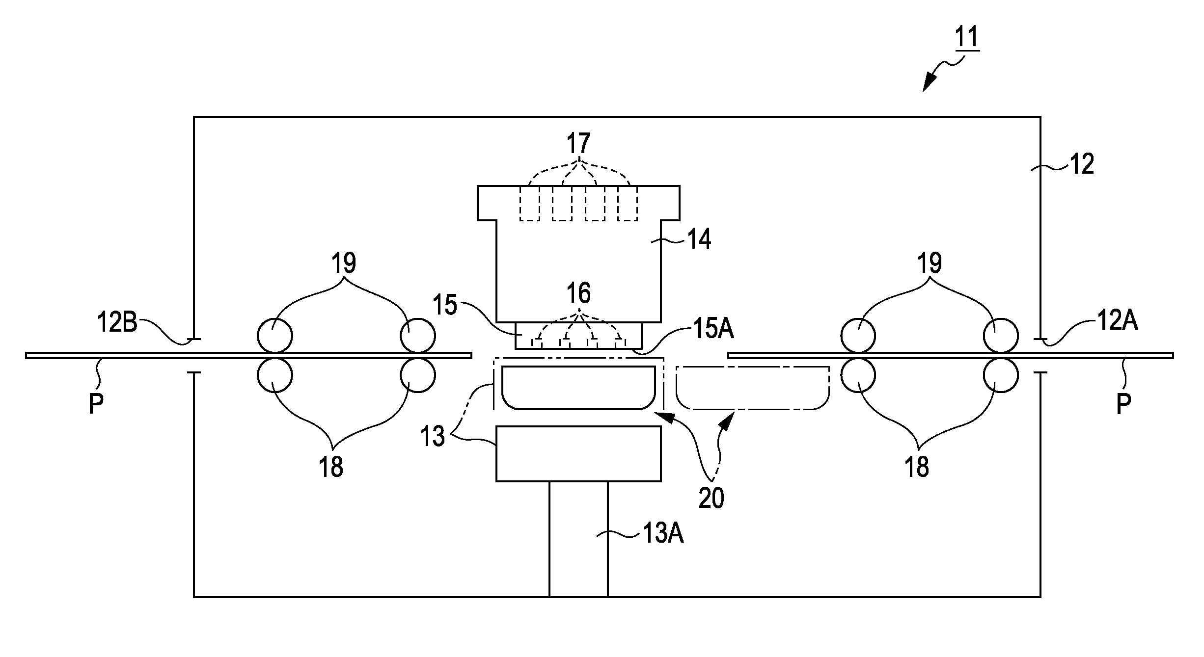
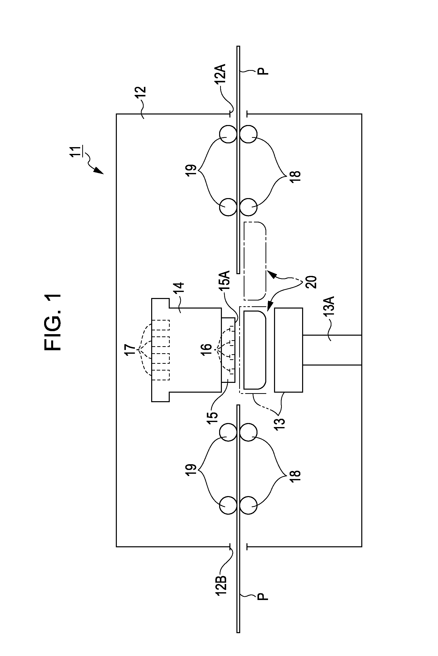
[0030]As shown in FIG. 1, a printer 11 has a box-shaped frame 12 serving as an exterior, and a support member 13 forming a rectangular shape when viewed from a plane is provided in a lower portion in the frame 12 from above. A longitudinal direction of the support member 13 corresponds to a horizontal direction in FIG. 1, and the support member 13 is vertically movable between a lower position shown by a solid line in FIG. 1 and an upper position shown by a two-dot chain line by a lifting device 13A.

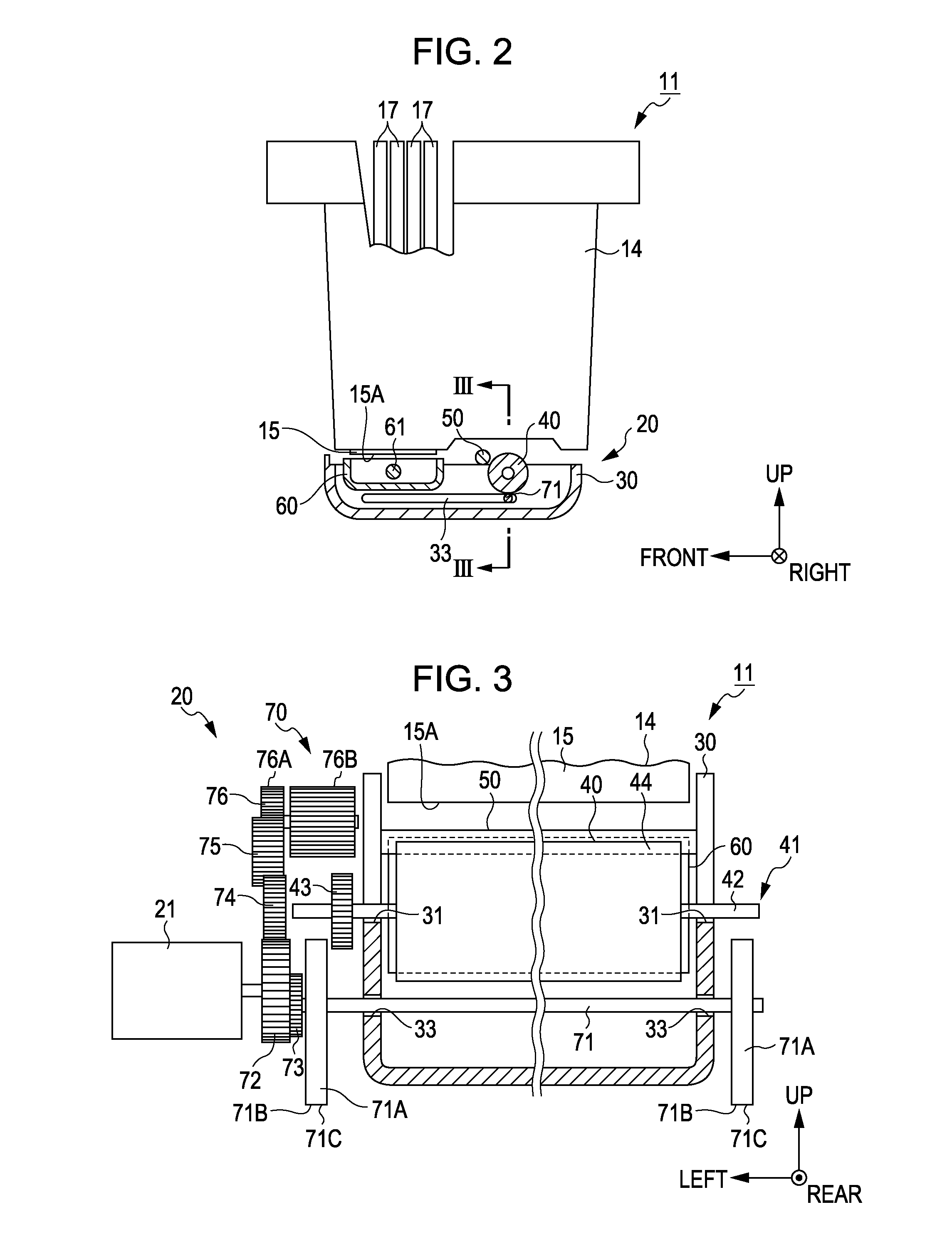
[0031]In the frame 12, at the position vertically facing an upper surface of the support member 13, a head cartridge 14 forming a rectangular box shape corresponding to the support member 13 is fixed, and a recording head 15 as an ejecting head is supported on the lower surface side of the head cartridge 14. On a no...

embodiment 2

[0070]The printer 11 of the embodiment differs from the head maintenance device 20 of Embodiment 1 in the following points. That is, the printer 11 of the embodiment has a transmission portion 170 instead of the transmission portion 70. Furthermore, the arrangement of the contact member 50 is changed. In addition, the details different from the printer 11 of Embodiment 1 will be described below, and the configurations common to Embodiment 1 are denoted by the same reference numerals, and a part or all of the descriptions thereof will be omitted.

[0071]As shown in FIG. 8, the contact member 50 is placed on the lower side and the rear side of the wiper 40. When being located at the upper position, the wiper 40 is farthest from the contact member 50 and comes into contact with the nozzle forming surface 15A. When being located at the lower position, the wiper 40 is nearest to the contact member 50 and does not come into contact with the nozzle forming surface 15A.

[0072]The transmission ...


PUM


Abstract

A printer includes a recording head having a nozzle forming surface formed with nozzles adapted to eject liquid; a wiper having an outer surface of a cylindrical surface shape capable of absorbing the ink attached to the nozzle forming surface; a motor that is driven, when moving the wiper in a direction in which the outer surface reaches the nozzle forming surface and in a direction in which the outer surface is separated from the nozzle forming surface, and is also driven when rotating the wiper; and a contact member coming into contact with the outer surface of the wiper rotated along with driving of the motor.

Description

BACKGROUND[0001]1. Technical Field[0002]The present invention relates to a liquid ejecting apparatus that has an absorbent member configured to absorb liquid attached onto a nozzle forming surface of an ejecting head.[0003]2. Related Art[0004]As the above-mentioned liquid ejecting apparatus, for example, an ink jet type printer disclosed in JPA-2005-305845 has been known. The absorbent member of the printer moves in a direction along the nozzle forming surface relative to the ejecting head. Moreover, the absorbent member effectively absorbs ink attached to the nozzle forming surface, by sliding on the nozzle forming surface and driven-rotating at the time of the relative movement.[0005]However, when the absorbent member remains in a state of containing the absorbed ink in large quantities, the absorbency of ink declines. For this reason, in order to squeeze the ink from the absorbent member, a configuration is considered which has a contact member capable of coming into contact with...

Claims


Application Information

Patent Timeline
Patent Type & Authority Applications(United States)
IPC IPC(8): B41J2/165
CPCB41J2/16517B41J2/16511
Inventor HIZAWA, SHUNICHITAKAHASHI, NOBUHITO
Owner SEIKO EPSON CORP
Why Eureka
Try Eureka