Current balance control for non-interleaved parallel bridge circuits in power converter

a power converter and current balance technology, applied in the direction of electric generator control, electric motor control, conversion with intermediate conversion to dc, etc., can solve the problems of current imbalance among current imbalance between and differences in the temperature of the switching elements used in the parallel bridge circuits to achieve the effect of reducing current imbalan

Active Publication Date: 2016-05-17
GENERAL ELECTRIC CO
View PDF24 Cites 3 Cited by
  • Summary
  • Abstract
  • Description
  • Claims
  • Application Information

AI Technical Summary

Benefits of technology

[0009]One exemplary aspect of the present disclosure is directed to a power converter system. The system includes a plurality of bridge circuits coupled in parallel. Each bridge circuit includes at least one switching element. The system further includes a control system configured to control pulse width modulation of the switching elements of the plurality of bridge circuits according to a substantially non-interleaved switching pattern. The control system is further configured to adjust timing of the control commands to reduce current imbalance between the plurality of bridge circuits coupled in parallel.
[0010]Another exemplary aspect of the present disclosure is directed to a method of providing an output power to a load. The method includes receiving, at a power converter, an alternating current power generated at generator. The method further includes converting, with the power converter, the alternating current power to an output power using a power converter. The power converter includes a plurality of bridge circuits coupled in parallel. Each bridge circuit includes a pair of switching elements coupled in series with one another. The method further includes receiving control commands to control pulse width modulation of the switching elements according to a substantially non-interleaved switching pattern and adjusting the timing of the control commands to reduce current imbalance between the plurality of bridge circuits coupled in parallel.
[0011]A further exemplary aspect of the present disclosure is directed to a doubly fed induction generator system. The doubly fed induction generator system includes a doubly fed induction generator configured to generate alternating current power. The system further includes a rotor side converter configured to receive the alternating current power and convert the alternating current power to a DC output. The power converter further includes a line side converter coupled to the rotor side converter via a DC bus. The line side converter is configured to receive the DC output from the rotor side converter and convert the DC power to an output power. At least one of the rotor side converter or the line side converter includes a plurality of bridge circuits coupled in parallel. Each bridge circuit includes a pair of switching elements coupled in series with one another. The power converter further includes a controller. The controller is configured to provide control commands to control pulse width modulation of the switching elements of the plurality of bridge circuits according to a substantially non-interleaved switching pattern. The controller is further configured to adjust the timing of the control commands to reduce current imbalance between the plurality of bridge circuits coupled in parallel.

Problems solved by technology

Operating parallel bridge circuits according to a non-interleaved switching pattern can still result in current imbalance among the parallel bridge circuits, particularly during transients (e.g. switching).
A number of factors can lead to this imbalance.
The circulating current can cause a current imbalance between the parallel bridge circuits.
The imbalance in current can result in a difference of temperatures in the switching elements used in the parallel bridge circuits, such as a difference in junction temperature of IGBTs used in the switching elements.
This reduces the overall output power capability of the power converter as the total output current capability is limited by the switching element with the highest temperature.

Method used


Image

  • Current balance control for non-interleaved parallel bridge circuits in power converter
  • Current balance control for non-interleaved parallel bridge circuits in power converter
  • Current balance control for non-interleaved parallel bridge circuits in power converter

Examples


Embodiment Construction

[0018]Reference now will be made in detail to embodiments of the invention, one or more examples of which are illustrated in the drawings. Each example is provided by way of explanation of the invention, not limitation of the invention. In fact, it will be apparent to those skilled in the art that various modifications and variations can be made in the present invention without departing from the scope or spirit of the invention. For instance, features illustrated or described as part of one embodiment can be used with another embodiment to yield a still further embodiment. Thus, it is intended that the present invention covers such modifications and variations as come within the scope of the appended claims and their equivalents.

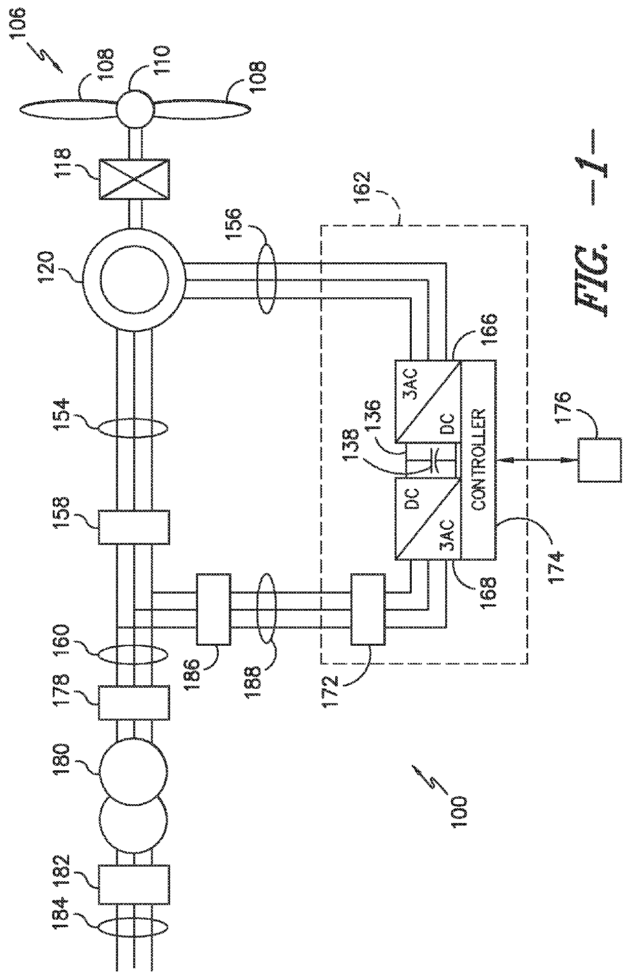
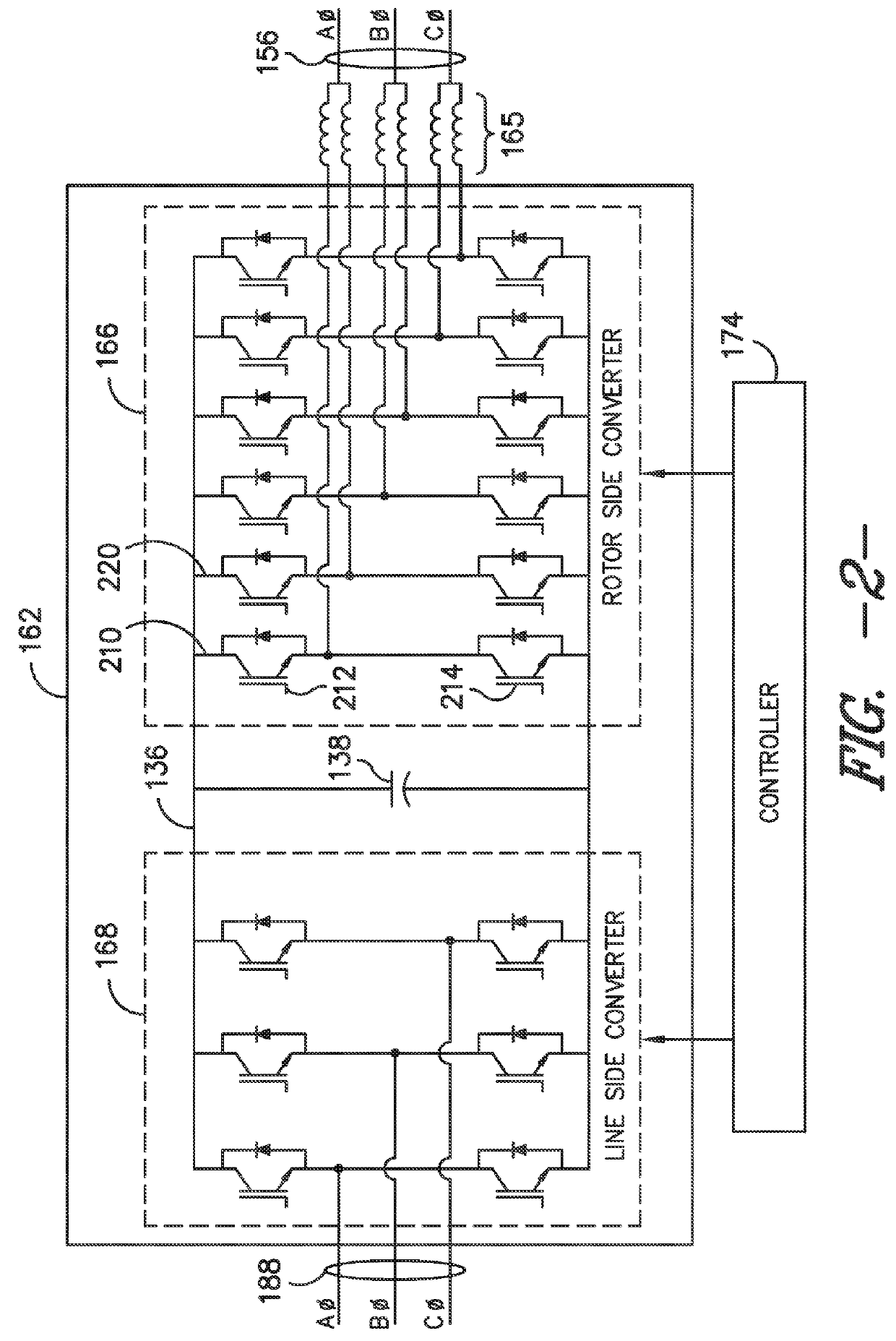
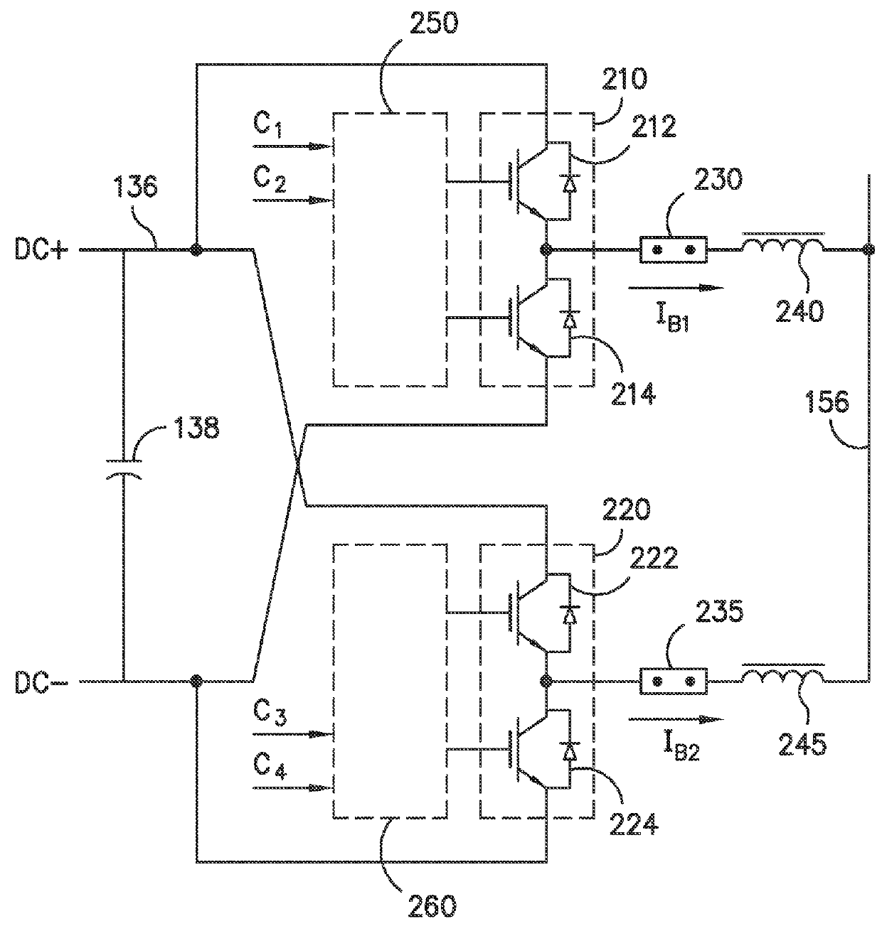
[0019]Generally, the present disclosure is directed to reducing current imbalance between parallel bridge circuits used in a power converter of a power generation system, such as a wind driven doubly fed induction generator (DFIG) system. The power converte...


PUM


Abstract

Systems and methods for reducing current imbalance between parallel bridge circuits used in a power converter of a power generation system, such as a wind driven doubly fed induction generator (DFIG) system, are provided. The power converter can include a plurality of bridge circuits coupled in parallel to increase the output power capability of the system. Each of the bridge circuits can include a pair of switching elements, such as insulated gate bipolar transistors (IGBTs), coupled in series with one another. The switching elements of the parallel bridge circuits can be controlled, for instance, using control commands (e.g. pulse width modulation commands) according to a substantially non-interleaved switching pattern. The timing of the control commands according to the substantially non-interleaved switching pattern can be adjusted to reduce current imbalance between the parallel bridge circuits.

Description

FIELD OF THE INVENTION[0001]The present disclosure relates generally to power converters, and more particularly to systems and methods of improving output power for a power converter in a power generation system, such as a wind driven doubly-fed induction generator system.BACKGROUND OF THE INVENTION[0002]Power systems often include a power converter that is configured to convert an input power into a suitable power for application to a load, such as a generator, motor, electrical grid, or other suitable load. For instance, a power generation system, such as a wind generation system, can include a power converter for converting alternating current power generated at the generator into alternating current power at a grid frequency (e.g. 50 / 60 Hz) for application to a utility grid. An exemplary power generation system can generate AC power using a wind driven doubly fed induction generator (DFIG). A power converter can regulate the flow of electrical power between the DFIG and the grid...

Claims


Application Information

Patent Timeline
Patent Type & Authority Patents(United States)
IPC IPC(8): H02M5/458H02M7/493H02M5/293H02M5/42H02P9/00H02P101/15
CPCH02M5/42H02M5/293H02M5/4585H02M7/493H02P9/007H02P2101/15H02P2207/073
Inventor WAGONER, ROBERT GREGORYKLODOWSKI, ANTHONY MICHAEL
Owner GENERAL ELECTRIC CO
Why Eureka
Try Eureka