

Program-controlled machine tool
a program-controlled machine tool and programming technology, applied in the direction of manufacturing tools, metal-working machine components, milling equipment, etc., can solve the problems of inability to achieve the optimal design of the workpiece table, and the universal design of the conventional universal milling machine and the machining center, so as to achieve good accessibility to the workpiece table and the working area, and high inherent rigidity
- Summary
- Abstract
- Description
- Claims
- Application Information
AI Technical Summary
Benefits of technology
Problems solved by technology
Method used
Image

Examples
Embodiment Construction
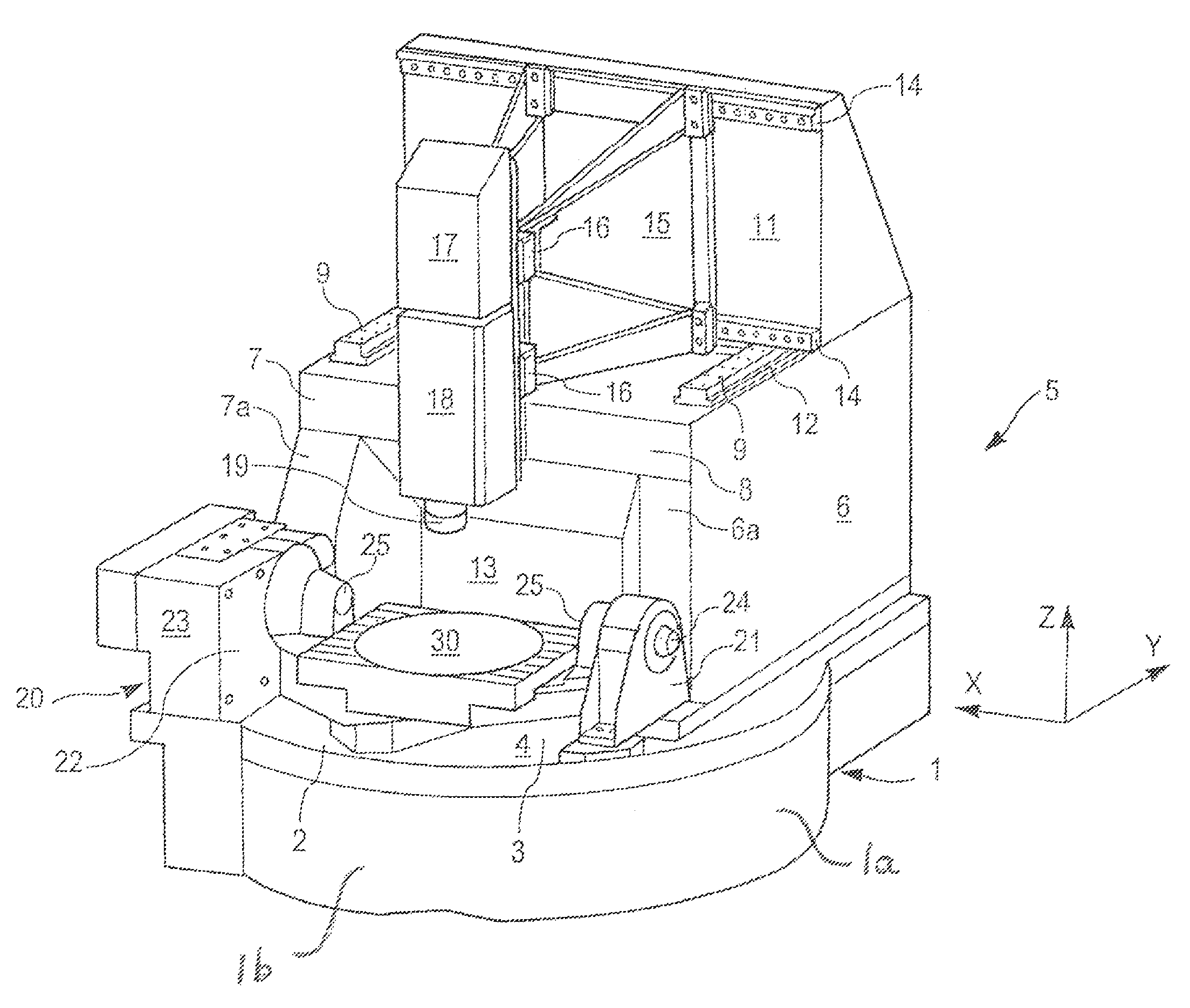
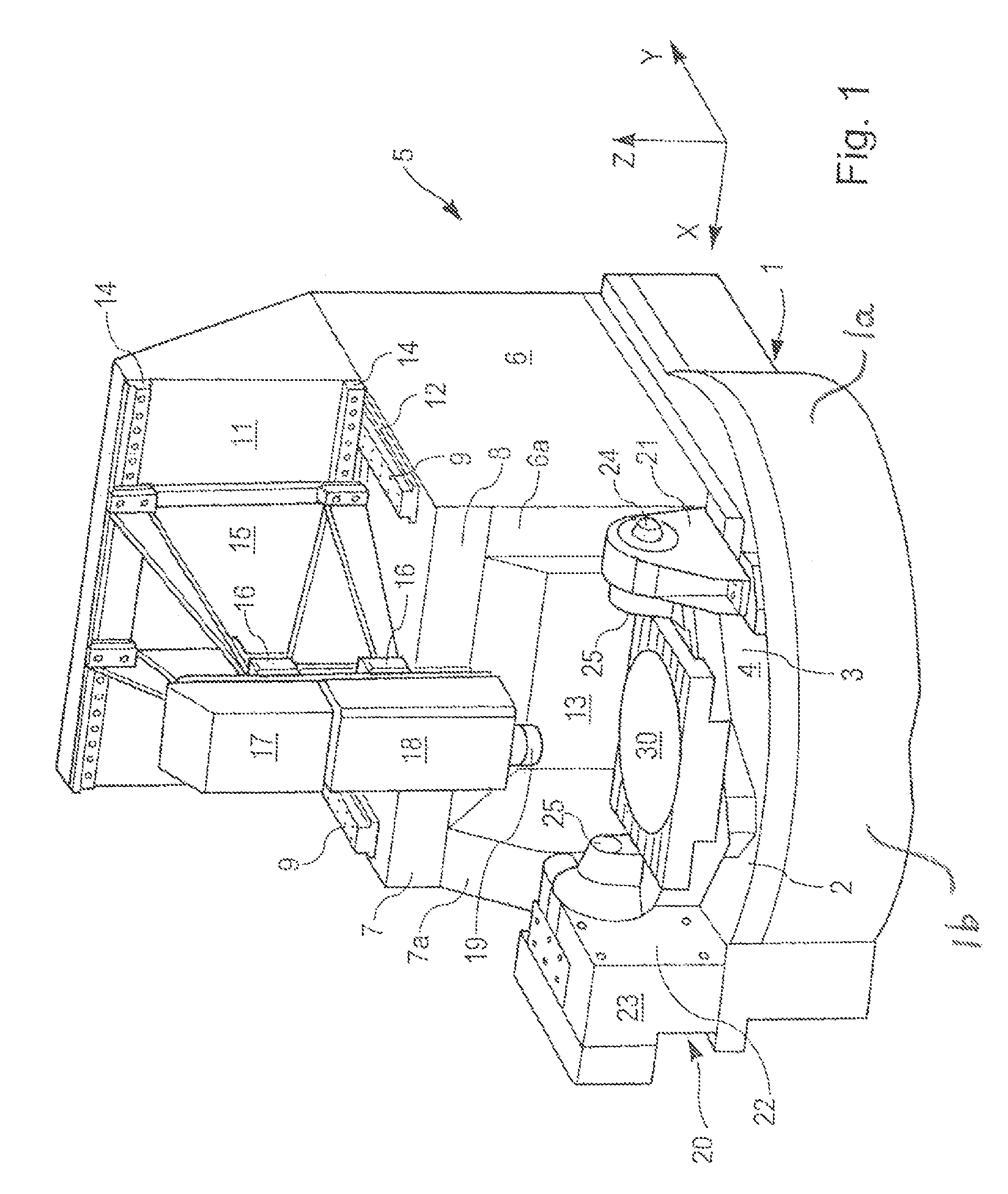
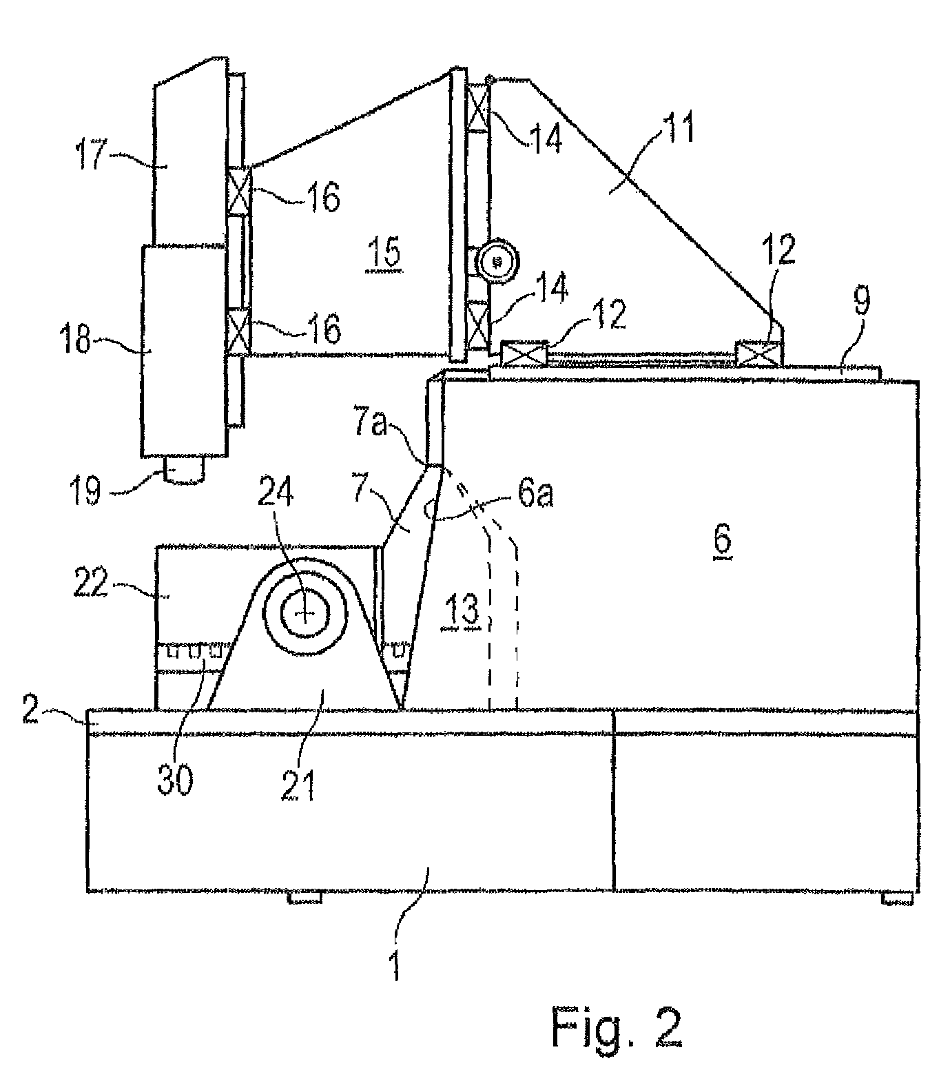
[0005]It is a purpose of embodiments of the invention to create a program controlled machine tool which, accompanied by a small place requirement and high inherent rigidity, has good accessibility to the workpiece table and to the working area so as to also be able to load bulky and heavy workpieces on the workpiece table by means of a crane or other lifting devices.
[0006]In a generic, program controlled machine tool, this purpose is achieved by the concepts disclosed herein. On the one hand, a high inherent rigidity of the machine structure is achieved by forming the substructure as a flat base having cylindrical side and front walls and is made in an integrated design with the rear machine frame. The small height of the base enables a good accessibility to the workpiece table and to the working area from above and from at least one side. Small dimensions of the machine result, inter alia, from the fact that the workpiece table is arranged on the front partial area of the base in f...
PUM
| Property | Measurement | Unit |
|---|---|---|
| area | aaaaa | aaaaa |
| length | aaaaa | aaaaa |
| diameter | aaaaa | aaaaa |
Abstract
Description
Claims
Application Information