Electric storage apparatus

a technology for electric storage and electric components, applied in electrical appliances, cell components, cell component details, etc., can solve problems such as increasing size, and achieve the effect of avoiding occupation of internal spa

Active Publication Date: 2016-05-24
GS YUASA INT LTD
View PDF8 Cites 2 Cited by
  • Summary
  • Abstract
  • Description
  • Claims
  • Application Information

AI Technical Summary

Benefits of technology

[0006]An object of the present invention is to provide an electric storage apparatus that prevents protrusion of a fixing member for fixing an accessory toward a battery cell and thereby avoids occupation of an internal space of the electric storage apparatus by the fixing member and damage to the battery cell caused by the fixing member.

Problems solved by technology

Therefore, a part of internal space of the module is occupied by the through bolts, disadvantageously causing increase in size.

Method used


Image

  • Electric storage apparatus
  • Electric storage apparatus
  • Electric storage apparatus

Examples


Embodiment Construction

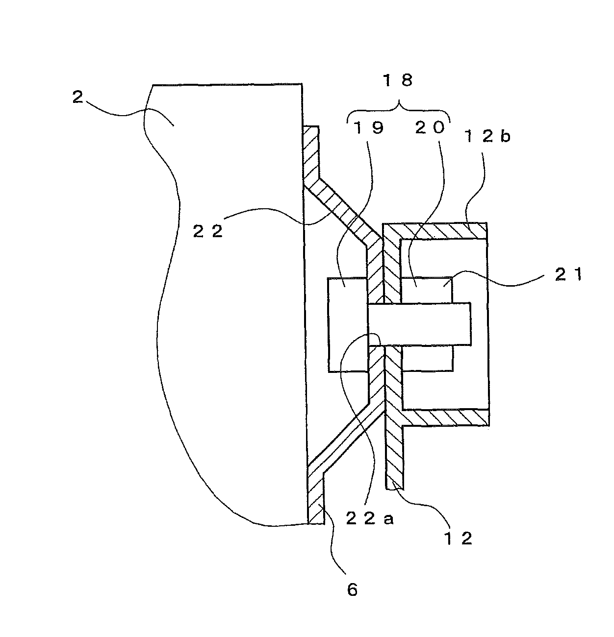
[0015]An aspect of the present invention provides an electric storage apparatus comprising, a battery cell, an accessory, a holding member for holding the battery cell and the accessory so that the battery cell and the accessory are on opposite sides, and a fixing member for fixing the accessory to the holding member, wherein a distance between the fixing member and the battery cell is set to be equal to or larger than a distance between the holding member and the battery cell.

[0016]With this arrangement, the fixing member is prevented from protruding toward the battery cell beyond the holding member. This can avoid that the fixing member interferes with the battery cell.

[0017]Preferably, the holding member has a recessed section for preventing the fixing member from protruding toward the battery cell.

[0018]With this arrangement, even when the holding member is thin, the recessed section can prevent the protrusion of the fixing member toward the battery cell by modifying an arrangem...


PUM

PropertyMeasurementUnit
areaaaaaaaaaaa
distanceaaaaaaaaaa
sectional areaaaaaaaaaaa

Abstract

An electric storage apparatus includes a battery cell, an accessory, a holding member for holding the battery cell and the accessory so that the battery cell and the accessory are on opposite sides, and a fixing member for fixing the accessory to the holding member. A distance between the fixing member and the battery cell is set to be equal to or larger than a distance between the holding member and the battery cell.

Description

CROSS-REFERENCE TO RELATED APPLICATIONS[0001]This application claims priority of Japanese Patent Application No.: 2012-253467 filed on Nov. 19, 2012, the content of which is incorporated herein by reference.FIELD[0002]The present invention relates to an electric storage apparatus.BACKGROUND[0003]Conventional battery modules as an example of an electric storage apparatus include a type where a plurality of battery cells are arranged in parallel and stored in a casing (Refer to, e.g., JP 2003-346749 A).[0004]However, in the conventional battery module as disclosed in JP 2003-346749 A, the battery cells are integrated by being held between resin frames (holding members) at both ends by use of through bolts disposed along the battery cells arranged in parallel. Therefore, a part of internal space of the module is occupied by the through bolts, disadvantageously causing increase in size. Disclosed in JP 2003-346749 A is that an electrical component (control device) is disposed in a side ...

Claims


Application Information

Patent Timeline
Patent Type & Authority Patents(United States)
IPC IPC(8): H01M2/10H01M50/209H01M50/227H01M50/262H01M50/278
CPCH01M2/1016H01M2/1022H01M2/1072H01M2/1077H01M50/227H01M50/262H01M50/278H01M50/209Y02E60/10
Inventor KUSUNOKI, TOSHIKI
Owner GS YUASA INT LTD
Why Eureka
Try Eureka