Tube-shell type heat exchanger with super-hydrophobic/hydrophilic surface

A technology of shell-and-tube heat exchangers and hydrophilic surfaces, which is applied to the types of heat exchangers, heat exchanger shells, indirect heat exchangers, etc., and can solve the problem of high operating costs and easy vibration of cross-flow shell-and-tube heat exchangers Flow dead zone, increase heat exchanger thermal resistance and other issues, to achieve the effect of facilitating heat transfer, not easy to deposit dirt, and reducing thermal resistance

Inactive Publication Date: 2018-05-11
SOUTH CHINA UNIV OF TECH
View PDF7 Cites 1 Cited by
  • Summary
  • Abstract
  • Description
  • Claims
  • Application Information

AI Technical Summary

Problems solved by technology

However, the cross-flow shell-and-tube heat exchanger has shortcomings such as large pressure drop, easy vibration, and inevitable flow dead zone, which leads to high operating costs and short maintenance cycles of the cross-flow shell-and-tube heat exchanger.
[0004] Traditional heat transfer tube bundle materials are mostly made of copper or stainless steel, and the heat transfer efficiency is limited. During the heat transfer process, a liquid with a higher temperature transfers heat to a liquid with a lower temperature, causing its temperature to rise rapidly, which will generate a large amount of heat. Bubbles, attached around the tube bundle, occupy the entire heat transfer tube bundle to form a layer of bubble layer, and the existence of the bubble layer causes uneven heat transfer, increases the thermal resistance of the heat exchanger, and greatly reduces the heat transfer coefficient

Method used


Image

  • Tube-shell type heat exchanger with super-hydrophobic/hydrophilic surface
  • Tube-shell type heat exchanger with super-hydrophobic/hydrophilic surface
  • Tube-shell type heat exchanger with super-hydrophobic/hydrophilic surface

Examples


Embodiment Construction

[0028] The present invention will be described in further detail below in conjunction with specific embodiments and accompanying drawings.

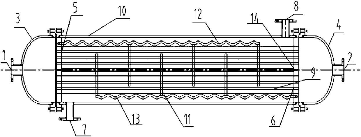
[0029] Such as figure 1 As shown, a shell-and-tube heat exchanger with a super-hydrophobic / hydrophilic surface includes a shell 10, and the two ends of the shell 10 respectively pass through the first tube sheet 5 and the second tube sheet 6 and use the method The flange connects the first head 3 and the second head 4, a shell-side coolant inlet pipe 7 is provided at the bottom of one end of the shell 10, and a shell-side coolant outlet pipe 8 is provided at the top of the other end of the shell. , the inlet end 2 and the outlet end 1 of the thermal fluid are respectively arranged at the horizontal ends of the first head 3 and the second head 4, and a plurality of heat exchange tube bundles 9 parallel to each other are arranged in the shell 10, and the heat exchange Both ends of the tube bundle are connected to the first tube sheet 5 and...


PUM


Abstract

The invention discloses a tube-shell type heat exchanger with a super-hydrophobic/hydrophilic surface. The tube-shell type heat exchanger comprises a shell, a first tube plate, a second tube plate, afirst end socket, a second end socket, and a heat exchange tube bundle arranged in the shell. The heat exchange tube bundle communicates with an inner cavity of the first end socket and an inner cavity of the second end socket. A patterned surface in a certain geometrical shape covers the surface of the heat exchange tube bundle, and super-hydrophobic areas and super-hydrophilic areas are distributed on the patterned surface at intervals. A first wave-shaped transverse plate and a second wave-shaped transverse plate which are arranged in parallel in the length direction and staggered by a certain distance are arranged in the shell. A baffle plate is arranged between the first wave-shaped transverse plate and the second wave-shaped transverse plate. The tube-shell type heat exchanger is simple in structure and easy to maintain, by the adoption of the super-hydrophobic/hydrophilic surface coating structure, the heat transfer coefficient of the tube bundle can be remarkably increased, andthe heat transfer effect is reinforced; and meanwhile, the pressure drop and flowing resistance are reduced to the greatest extent, flowing dead zones are eliminated easily, the heat exchange area isincreased, the heat exchange efficiency is improved, and the tube-shell type heat exchanger is resistant to high temperature and high pressure, even in heat exchange and good in stability.

Description

technical field [0001] The invention relates to a heat exchanger and heat transfer enhancement and energy-saving technology, in particular to the preparation of a super-hydrophobic / hydrophilic high-efficiency heat transfer coating and a shell-and-tube heat exchanger with a new structure. Background technique [0002] As a kind of heat exchange equipment, heat exchanger is widely used in chemical industry, aerospace, refrigeration, metallurgy and many other industries. Compared with other types of heat exchangers, shell and tube heat exchangers have the characteristics of mature technology, reliable structure, and easy maintenance, and are most widely used in industrial production. Due to the diversity of use conditions (corrosion, temperature, pressure, medium, impurities, heat exchange capacity, etc.), heat exchangers need to be reasonably designed and optimized. Shell and tube heat exchanger is one of the most widely used heat transfer equipment at present. It is an energ...

Claims


Application Information

Patent Timeline
Patent Type & Authority Applications(China)
IPC IPC(8): F28D7/16F28F9/24F28F9/02
CPCF28D7/16F28F9/0229F28F9/24
Inventor 蒋翔赵飞孙敬知
Owner SOUTH CHINA UNIV OF TECH
Why Eureka
Try Eureka