In-line plasma CVD device

A technology of chemical vapor deposition and plasma, which is applied in gaseous chemical plating, electrical components, semiconductor/solid-state device manufacturing, etc. It can solve problems such as scattering of accumulations, increase of resistance on the inner wall of the chamber, and unstable generation of plasma.

Inactive Publication Date: 2015-09-09
KOBE STEEL LTD
View PDF10 Cites 13 Cited by
  • Summary
  • Abstract
  • Description
  • Claims
  • Application Information

AI Technical Summary

Problems solved by technology

As a result, there is a problem that thickly attached deposits are scattered
In addition, when the formed film has insulating properties, even if the film is on the chamber side, since it exists in the part where power flows, the resistance of the inner wall of the chamber increases.
Therefore, the generation of plasma using the inner wall as one electrode becomes unstable, and there is a possibility that the operating conditions may deviate from the optimum conditions.

Method used


Image

  • In-line plasma CVD device
  • In-line plasma CVD device
  • In-line plasma CVD device

Examples


no. 1 Embodiment approach

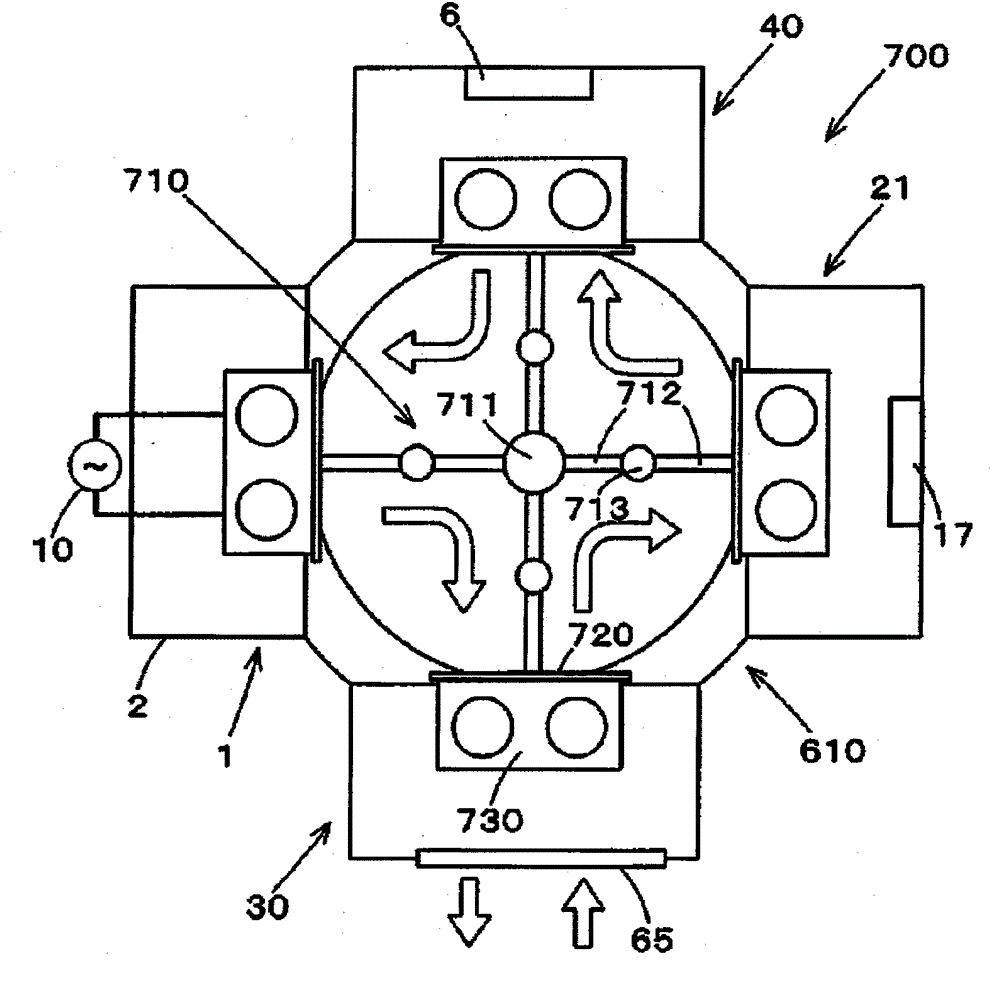
[0036] figure 1 It is a perspective view showing the overall structure of the plasma chemical vapor deposition apparatus 100 according to the first embodiment of the present invention, figure 2 is its top view.

[0037] The plasma chemical vapor deposition apparatus 100 includes a film forming chamber 1 having a plasma chemical vapor deposition mechanism, a load-lock vacuum chamber 20 as a separate compartment arranged on the upstream side of the film forming chamber 1, and a film forming chamber 20 arranged on the film forming chamber. A load-lock vacuum chamber (compartment) 30 as a separate compartment on the downstream side of the chamber 1 . The upstream and downstream described here refer to the direction in which the substrate W is transported. An isolation valve 41 is arranged at the entrance of the load-lock vacuum chamber 20, an isolation valve 42 is arranged between the outlet of the load-lock vacuum chamber 20 and the entrance of the film forming chamber 1, and ...

no. 2 Embodiment approach

[0103] Below, yes Figure 5A ~ Figure 5D The plasma chemical vapor deposition apparatus 200 according to the second embodiment of the present invention will be described. The plasma chemical vapor deposition apparatus 200 of the second embodiment is different from the plasma chemical vapor deposition apparatus 100 of the above-mentioned first embodiment in the arrangement of the substrate W on the substrate stage. Other than that, it is the same as that of the first embodiment, so the description will not be repeated here about the part that overlaps with the above description.

[0104] Figure 5A The plasma chemical vapor deposition apparatus 200 of the second embodiment is shown. Should Figure 5A corresponds to Figure 4A .

[0105] Such as Figure 5A As shown, the plasma chemical vapor deposition apparatus 200 includes: a chamber having a vacuum chamber 202 as a film forming chamber 201 including a plasma chemical vapor deposition mechanism; a load-lock vacuum chambe...

no. 3 Embodiment approach

[0109] Below, yes Figure 6A The plasma chemical vapor deposition apparatus 300 according to the third embodiment of the present invention shown will be described. This plasma chemical vapor deposition apparatus 300 is different from the plasma chemical vapor deposition apparatus 100 of the above-mentioned first embodiment in the arrangement of the substrate W. Other than that, it is the same as that of the first embodiment, so the description will not be repeated here about the part that overlaps with the above description.

[0110] Figure 6A The plasma chemical vapor deposition apparatus 300 of the third embodiment is shown. Should Figure 6A is corresponding to Figure 4A A plan view for explaining the operating state of the continuous plasma chemical vapor deposition apparatus.

[0111] Such as Figure 6A As shown, the plasma chemical vapor deposition apparatus 300 includes: a chamber having a vacuum chamber 302 as a film forming chamber 301 including a plasma chemi...


PUM


Abstract

Provided is an in-line plasma CVD device (100) capable of performing a deposition process at a high production efficiency while maintaining stable deposition conditions, without spending time and energy on cleaning and the like even when in use for a long time. This plasma CVD device (100) is equipped with a deposition chamber (1) and load-lock chambers (20, 30) which are separate from the deposition chamber (1). The device (100) is of the in-line-type for conveying a substrate between these chambers and producing a film on the substrate. The deposition chamber (1) is equipped with a vacuum chamber (2), a vacuum exhaust means (3) for discharging the air inside the vacuum chamber (2), a gas supply unit (9) for supplying a starting-material gas into the vacuum chamber (2), and a plasma generation power source (10) for generating plasma inside the vacuum chamber (2). Substrates in the deposition chamber (1) are divided into a first group (18) connected to one pole of the plasma generation power source (10), and a second group (19) connected to the other pole of the plasma generation power source (10). The plasma is produced between the first group (18) and the second group (19) which have different polarities from one another.

Description

technical field [0001] The present invention relates to a plasma chemical vapor deposition device for forming a chemical vapor deposition film on a substrate, and in particular to a continuous plasma chemical vapor deposition device with high production efficiency while maintaining stable film forming conditions. Background technique [0002] For automotive engine parts such as piston rings, good wear resistance, heat resistance, anti-seizing properties, etc. are required. Therefore, these mechanical parts are coated with wear resistance such as DLC (Diamond-Like-Carbon) using plasma chemical vapor deposition. [0003] In addition, when performing the plasma chemical vapor deposition method on the above-mentioned substrates, it is desirable to accommodate a large number of substrates in a vacuum chamber and process them at one time in consideration of productivity. When a large number of substrates are processed at one time in this way, it is necessary to make the thickness...

Claims


Application Information

Patent Timeline
Patent Type & Authority Applications(China)
IPC IPC(8): C23C16/458C23C16/44C23C16/503
CPCC23C16/4409C23C16/54C23C16/505C23C16/26C23C16/4401C23C16/4588H01J37/32568H01J37/32706H01J37/32779H01J37/32899H01J37/32715H01J37/32853H01L21/67173H01L21/67201H01L21/67754H01L21/6776C23C16/4412C23C16/4584C23C16/503
Inventor 玉垣浩芳贺润二
Owner KOBE STEEL LTD
Why Eureka
Try Eureka