Piezoelectric/electrostrictive device

a technology of electro-electrostrictive devices and electrodes, which is applied in piezoelectric/electrostrictive/magnetostriction machines, piezoelectric/electrostriction/magnetostriction machines, electrical equipment, etc., can solve the problems of incorrect reading/writing of information, weakening of the electric field formed between the electrodes, and reducing the voltage between the electrodes, so as to ensure the surface area increase the rate of the lateral end

Inactive Publication Date: 2007-08-16
NGK INSULATORS LTD
View PDF7 Cites 11 Cited by
  • Summary
  • Abstract
  • Description
  • Claims
  • Application Information

AI Technical Summary

Benefits of technology

[0011] In view of the above situation, an object of the present invention is to provide a piezoelectric / electrostrictive device which can effectively suppress the deposition of moisture on the lateral end surfaces of piezoelectric / electrostrictive elements and dust generation from the lateral end surfaces.
[0013] In general, when moisture deposits on a surface, the moisture tends to hardly deposit as the actual surface area of the surface (namely, the total surface area obtained by three-dimensionally taking all the large and small bumps and dips on the surface into consideration) reduces. Hence, it can be said that moisture tends to hardly deposit on the lateral end surfaces of a piezoelectric / electrostrictive element as the actual surface area of the lateral end surfaces reduces.
[0016] In addition, the present inventors have found that the actual surface area (namely, surface area increase rate) of the lateral end surfaces of a piezoelectric / electrostrictive element strongly correlates with the extent of the particle separation from the lateral end surfaces and the particle separation (namely, dust generation) from the lateral end surfaces can effectively be suppressed as long as the surface area increase rate is “four” or less.
[0017] Hence, by the above configuration, it is possible to effectively suppress the deposition of moisture onto the lateral end surfaces of a piezoelectric / electrostrictive element and dust generation from the lateral end surfaces. As a result, the intended operation of the piezoelectric / electrostrictive device is maintained for a long period of time. In other words, it is possible to provide a highly-durable piezoelectric / electrostrictive device. In addition, it is possible to provide a piezoelectric / electrostrictive device which can be used in an environment where dust generation should be avoided to the utmost.
[0019] That is, the present invention, by such a production method, can provide a piezoelectric / electrostrictive device, wherein the lateral end surfaces of piezoelectric / electrostrictive elements are formed by applying prescribed specific processing to cut planes formed by cutting the laminated body comprising electrodes and piezoelectric / electrostrictive layers.
[0021] By adopting any one of the above processing (or a combination of two or more kinds of the processing) as the above specific processing, it is possible to surely control the surface area increase rate of the lateral end surfaces of a piezoelectric / electrostrictive element to “four” or less through relatively simple treatment.

Problems solved by technology

When such electric leakage occurs, voltage between the electrodes lowers and thereby the strength of the electric field formed between the electrodes weakens.
In addition, when such an above-disclosed piezoelectric / electrostrictive device is used as, for example, an actuator for the positioning of the magnetic head of a hard disk drive, the attachment of debris, dust, or the like on a hard disk, etc., may cause incorrect reading / writing of information.

Method used


Image

  • Piezoelectric/electrostrictive device
  • Piezoelectric/electrostrictive device
  • Piezoelectric/electrostrictive device

Examples


Embodiment Construction

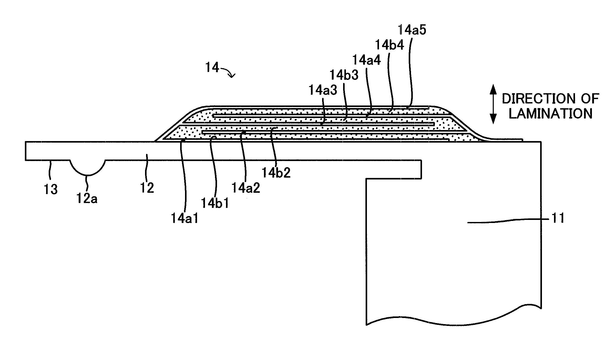
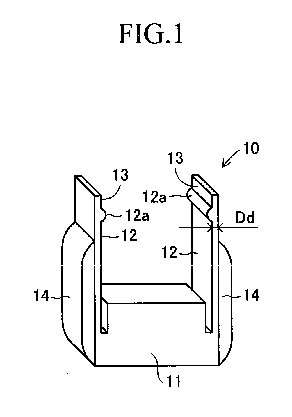
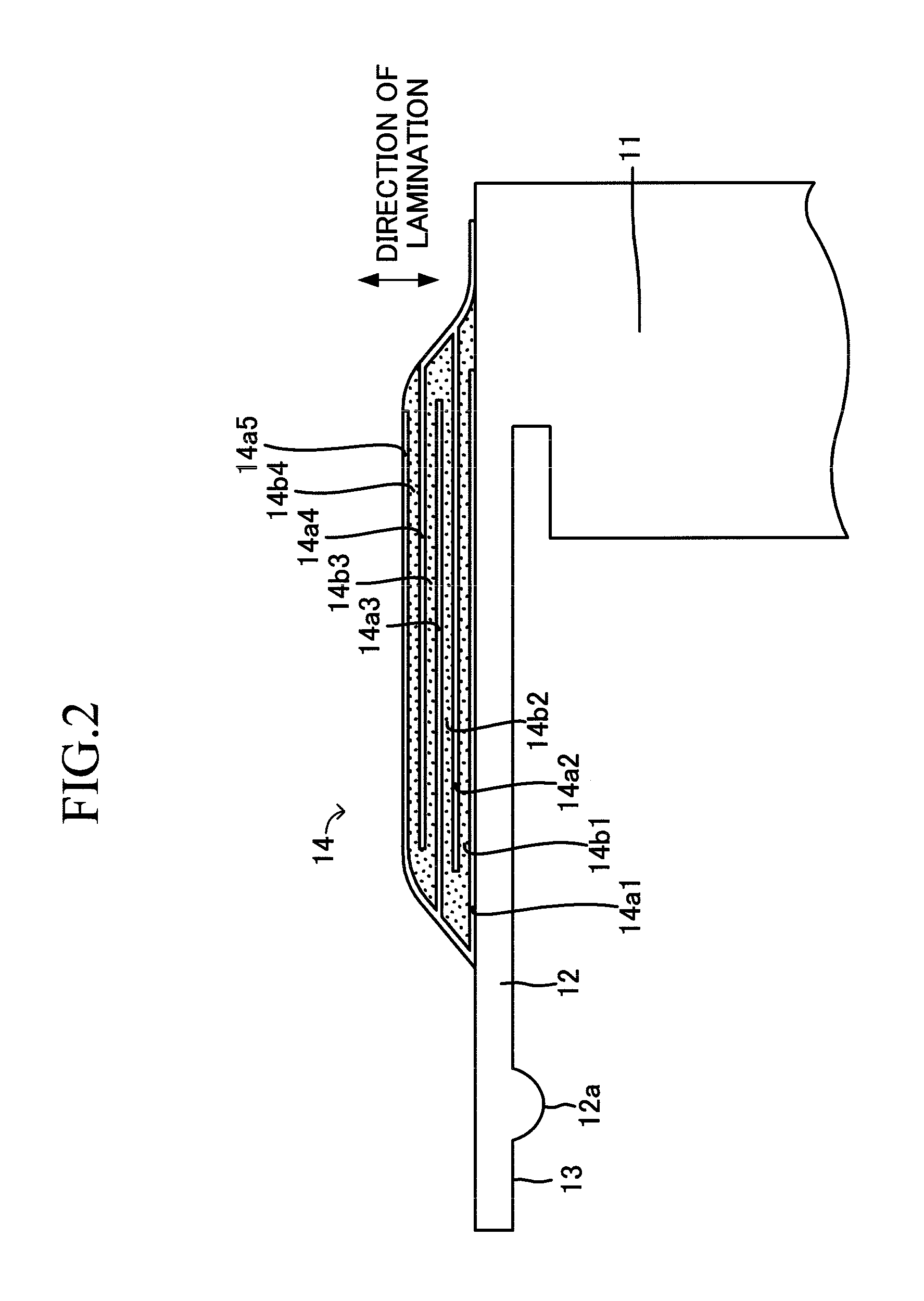
[0041] Embodiments of piezoelectric / electrostrictive devices according to the present invention are hereunder explained in reference to drawings. A piezoelectric / electrostrictive device 10 according to the present embodiment shown as a perspective view in FIG. 1 comprises: a stationary portion 11 of a rectangular solid; a pair of thin-plate portions 12 being supported with the stationary portion 11 so as to stand from the stationary portion and facing each other; holding portions (movable portions) 13 formed at the insides on the tip side from the protrusions 12a formed at the insides in the vicinities of the tips of the thin-plate portions 12; and piezoelectric / electrostrictive elements 14 formed at least on respective outer planes of the thin-plate portions 12 by alternately laminating laminar electrodes and piezoelectric / electrostrictive layers. The outline of such a configuration is disclosed in, for example, Japanese Patent Application Laid-Open (kokai) No. 2001-320103.

[0042] ...


PUM

PropertyMeasurementUnit
curvature radiusaaaaaaaaaa
lengthaaaaaaaaaa
surface roughnessaaaaaaaaaa

Abstract

A piezoelectric / electrostrictive device is provided with a stationary portion, a thin-plate portion supported by the stationary portion, and piezoelectric / electrostrictive element formed by alternately laminating a plurality of electrodes and a plurality of piezoelectric / electrostrictive layers. The piezoelectric / electrostrictive device is produced by cutting a thin-plate body that composes the thin-plate portion afterward and a laminated body comprising the piezoelectric / electrostrictive layers and thereafter applying prescribed specific processing (for example, heat treatment) to the cut plane (the lateral end surfaces). By so doing, the ratio of the actual surface area of the lateral end surface of the piezoelectric / electrostrictive element to the area of the lateral end surface of the piezoelectric / electrostrictive element in the orthographic projection is four or less, and the deposition of moisture on the lateral end surfaces is suppressed to the extent of not substantially generating electric leakage or ion migration. As a result, a highly durable piezoelectric / electrostrictive device can be provided.

Description

TECHNICAL FIELD [0001] The present invention relates to a piezoelectric / electrostrictive device including a stationary portion, a thin-plate portion supported by the stationary portion, and a piezoelectric / electrostrictive element including laminar electrodes and a piezoelectric / electrostrictive layer. BACKGROUND ART [0002] Piezoelectric / electrostrictive devices of the above-described type have been actively developed as an actuator for precision machining; as an actuator for controlling the position of a read and / or write element (e.g., a magnetic head of a hard disk drive) for reading and / or writing optical information, magnetic information, or the like; as a sensor for converting mechanical vibration to an electrical signal; or as a similar device. [0003] Japanese Patent Application Laid-Open (kokai) No. 2001-320103 discloses an example of such a piezoelectric / electrostrictive device, which is shown in FIG. 13. The piezoelectric / electrostrictive device includes a stationary porti...

Claims


Application Information

Patent Timeline
Patent Type & Authority Applications(United States)
IPC IPC(8): H01L41/047H01L41/25H01L41/314H01L41/43
CPCH01L41/43H01L41/094Y10T29/42H01L41/314H01L41/25H10N30/2042H10N30/03H10N30/074H10N30/097
Inventor IKEDA, KOJIKIKUTA, YUYANOGUCHI, NOBUCHIKAKITAMURA, KAZUMASASHIBATA, KAZUYOSHI
Owner NGK INSULATORS LTD
Why Eureka
Try Eureka