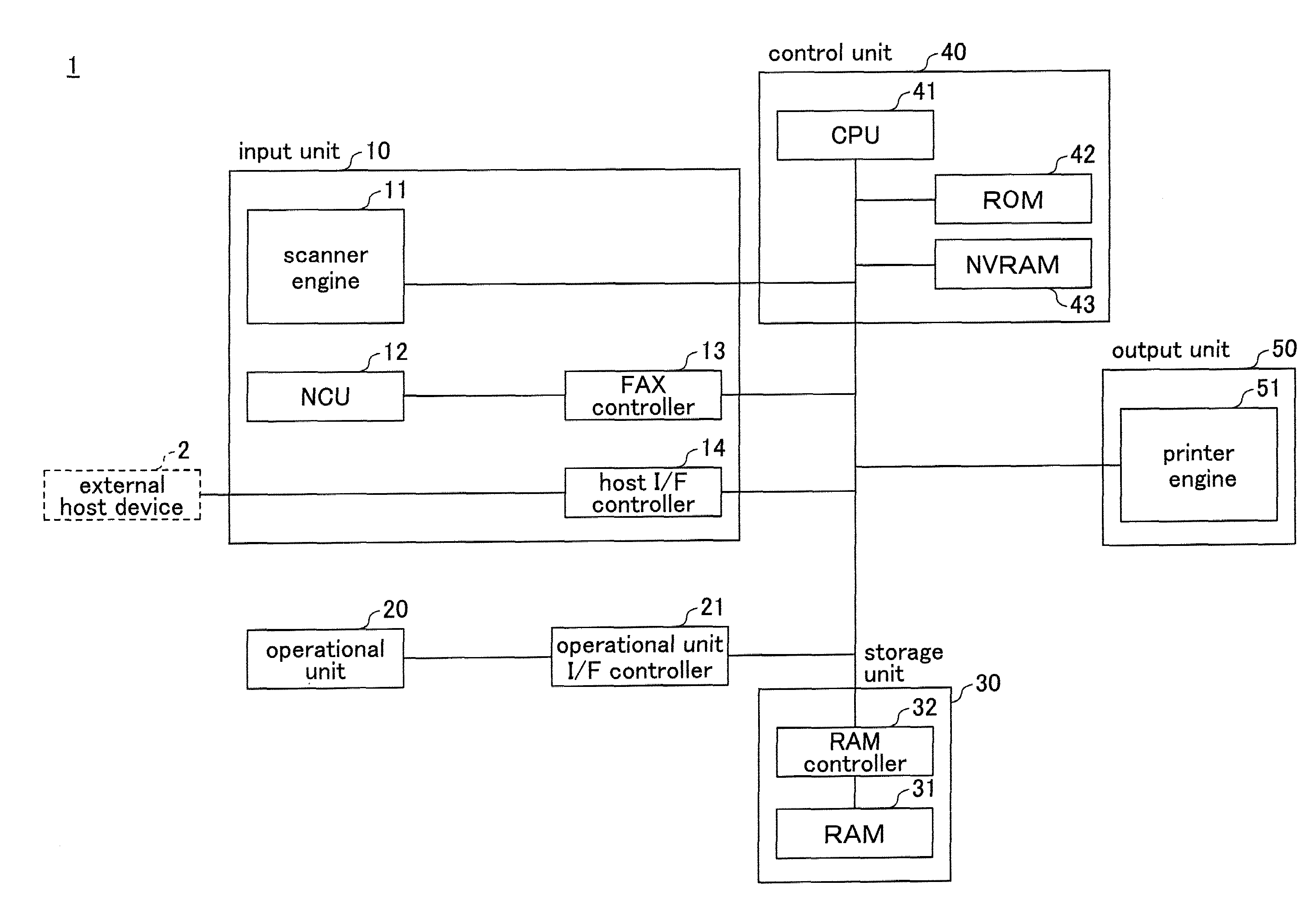
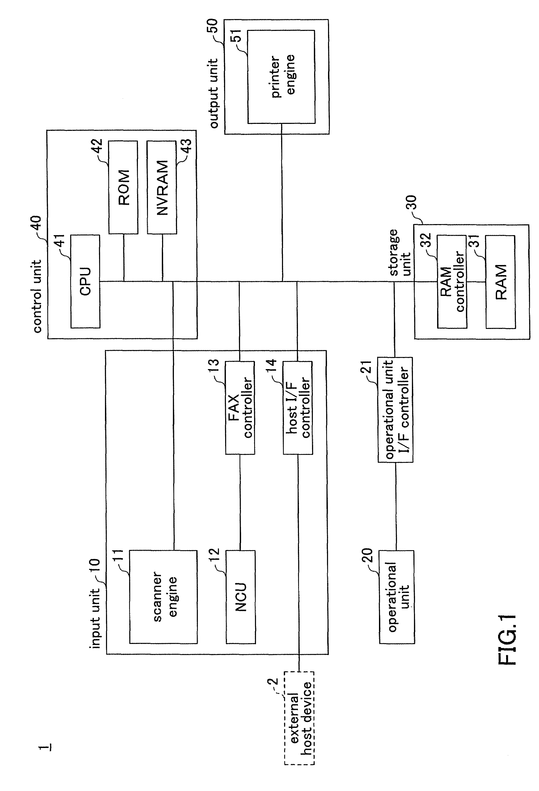
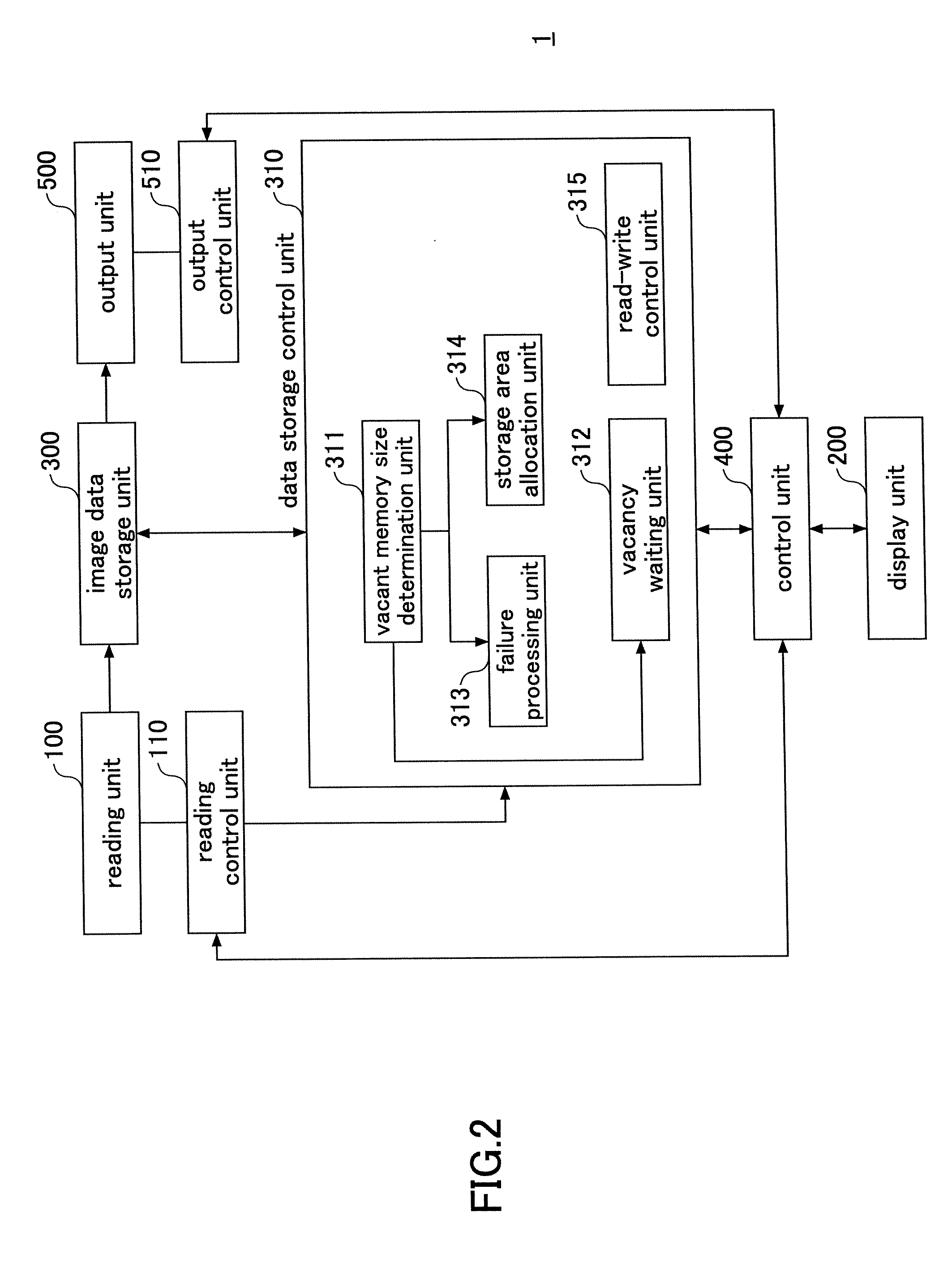
Image forming device

a technology of image forming and forming tubes, which is applied in the direction of digital output to print units, visual presentations, instruments, etc., can solve the problems of affecting the effect of sorting function, affecting the number of pages able to be stored, and interrupting the image forming process, so as to prevent the operation from halting

Inactive Publication Date: 2008-10-16
RICOH KK
View PDF3 Cites 1 Cited by
  • Summary
  • Abstract
  • Description
  • Claims
  • Application Information

AI Technical Summary

Benefits of technology

[0029]According to the embodiment, the method for allocating a storage area changes in the collective mode. Hence, it is possible to prevent halt of operations due to full occupation of a memory, and able to prevent the full occupation of the memory.

Problems solved by technology

However, for an image forming device having a small storage size, the number of pages able to be stored is limited, and when reading a manuscript, capacity overflow may occur, which may interrupt the image forming process.
For this reason, it is difficult to effectively realize the sorting function, and the needs of users cannot be satisfied.
However, in the technique disclosed in reference 1, since the system continues to wait as long as the residual memory size is less than the preset value, for example, during copying operations, a problem may occur that the copying operations may be halted if the memory does not have a sufficient vacancy for a long time, namely, the system is trapped by the condition that the memory does not have a vacancy sufficiently larger than the preset value, and the system is halted.

Method used


Image

  • Image forming device
  • Image forming device
  • Image forming device

Examples


example 1

of Operations of Printer 1

[0125]Below, an example of operations of the printer 1 is described with reference to FIG. 7.

[0126]FIG. 7 is a flowchart illustrating an example of the operations of the printer 1, as an example of the image forming device of the embodiment of the present invention.

[0127]In this example, the first method or the second method for allocating a storage area in the image data storage unit 300 is selected depending on the current printing mode of the printer 1, namely, a one-side mode or a two-side mode.

[0128]As shown in FIG. 7, in step S3001, the control unit 400 determines the current printing mode of the printer 1, that is, a one-side mode or a two-side mode.

[0129]If it is determined that the current printing mode of the printer 1 is the one-side mode, the procedure proceeds to step S3002.

[0130]If it is determined that the current printing mode of the printer 1 is the two-side mode, the procedure proceeds to step S3006.

[0131]In step S3002, the control unit 40...

example 2

of Operations of Printer 1

[0156]Below, another example of operations of the printer 1 is described with reference to FIG. 9.

[0157]FIG. 9 is a flowchart illustrating a second example of the operations of the printer 1, as an example of the image forming device of the embodiment of the present invention.

[0158]In this example, the first method or the second method for allocating a storage area in the image data storage unit 300 is selected depending on a printing mode (image forming condition) of a sort mode or a stack mode.

[0159]As shown in FIG. 9, in step S4001, when a copy operation starts, the control unit 400 determines the current printing mode of the printer 1, that is, a sort mode or a stack mode.

[0160]If it is determined that the current printing mode of the printer 1 is the stack mode, the procedure proceeds to step S4002.

[0161]If it is determined that the current printing mode of the printer 1 is the sort mode, the procedure proceeds to step S4006.

[0162]In step S4002, the co...

example 3

of Operations of Printer 1

[0174]Below, a third example of operations of the printer 1 is described with reference to FIG. 10.

[0175]FIG. 10 is a flowchart illustrating a third example of the operations of the printer 1, as an example of the image forming device of the embodiment of the present invention.

[0176]In this example, the printer 1 is set in advance in a collective printing mode, in which plural image data sets are collected for printing. In this example, the first method or the second method for allocating a storage area in the image data storage unit 300 is selected depending on whether an image to be read is the first one of the images to be collected.

[0177]As shown in FIG. 10, in step S5001, when a copy operation starts, the control unit 400 determines whether the current image is the first one of the images to be collected.

[0178]If it is determined that the current image is the first one of the images to be collected, the procedure proceeds to step S5002.

[0179]If it is d...


PUM


Abstract

An image forming device is disclosed that is able to prevent halt of operations due to full memory occupation, and prevent the full occupation of the memory. The image forming device includes a reading unit; an image data storage unit; a vacancy waiting unit that, when allocating a storage area for storing image data in the image data storage unit, waits until the storage size of a vacancy in the image data storage unit becomes greater than a predetermined value when allocation of the storage area fails; a failure processing unit that, when allocating the storage area for storing the image data in the image data storage unit, performs failure processing when allocation of the storage area fails; and a control unit that controls one of the vacancy waiting unit and the failure processing unit according to image forming conditions in the image forming device.

Description

CROSS-REFERENCE TO RELATED APPLICATIONS[0001]The present patent application claims priority under 35 U.S.C. §119 from Japanese Patent Application No. 2006-280674, filed on Oct. 13, 2006 in the Japan Patent Office, the contents and disclosures of which are hereby incorporated by reference herein in their entirety.BACKGROUND OF THE INVENTION[0002]1. Field of the Invention[0003]The present invention relates to an image forming device.[0004]2. Description of the Related Art[0005]In copiers or other image forming devices of the related art, once image data for forming an image are all stored in a memory, image forming processing is performed on the stored image data. In this case, in order to realize functions of processing data equivalent to plural pages (for example, a sorting function), it is necessary to have a storage size for storing the data equivalent to plural pages. However, for an image forming device having a small storage size, the number of pages able to be stored is limite...

Claims


Application Information

Patent Timeline
Patent Type & Authority Applications(United States)
IPC IPC(8): G06F15/00
CPCH04N1/00477H04N1/32363H04N1/32448H04N1/32496H04N2201/0094H04N2201/0098H04N2201/3288H04N2201/3298H04N2201/33335
Inventor KAKOI, AKIHIROASAKAWA, TETSUOKOUCHI, MIKINAKAMURA, RIEFURUICHI, YOSHINORINOGUCHI, DAISUKE
Owner RICOH KK
Why Eureka
Try Eureka