
Relay server and relay communication system

a relay communication system and relay technology, applied in the field of relay servers, can solve problems such as complex processes

Active Publication Date: 2016-05-17
MURATA MASCH LTD
View PDF9 Cites 1 Cited by
  • Summary
  • Abstract
  • Description
  • Claims
  • Application Information

AI Technical Summary

Benefits of technology

The present invention provides a relay server that eliminates the need to update a gateway table when a VPN is built. This is achieved by associating the virtual address with the relay server's address in a gateway table, which is used to connect to the network. By doing this, the setting of the gateway table is eliminated, saving time and preventing the assignment of unnecessary virtual addresses. This results in efficient communication and simplified management of communication. The invention also allows for flexible communication based on network environments and the status of the address. Overall, the invention simplifies and streamlines the process of setting up and communicating through VPNs.

Problems solved by technology

Therefore, the gateway table needs to be updated each time a VPN is built, which results in a complicated process.

Method used


Image

  • Relay server and relay communication system
  • Relay server and relay communication system
  • Relay server and relay communication system

Examples


Embodiment Construction

[0039]Next, preferred embodiments of the present invention will be described with reference to the drawings. Firstly, with reference to FIG. 1, an outline of a relay communication system 100 according to the present preferred embodiment will be described. FIG. 1 is an explanatory diagram showing an overall configuration of a relay communication system 100 according to this preferred embodiment.

[0040]As shown in FIG. 1, the relay communication system 100 includes a plurality of LANs 10, 20, and 30 that are connected to a Wide Area Network (WAN, Wide Area Network) 80. Each of the LANs 10, 20, and 30 is a relatively small network built in a limited place. The LANs 10, 20, and 30 are located in physically distant places. In this preferred embodiment, the Internet is preferably used as the WAN 80.

[0041]In the following, a specific description will be provided for each of the LANs. As shown in FIG. 1, a relay server (second relay server) 1, operation PCs 11 and 12 serving as second routin...


PUM


Abstract

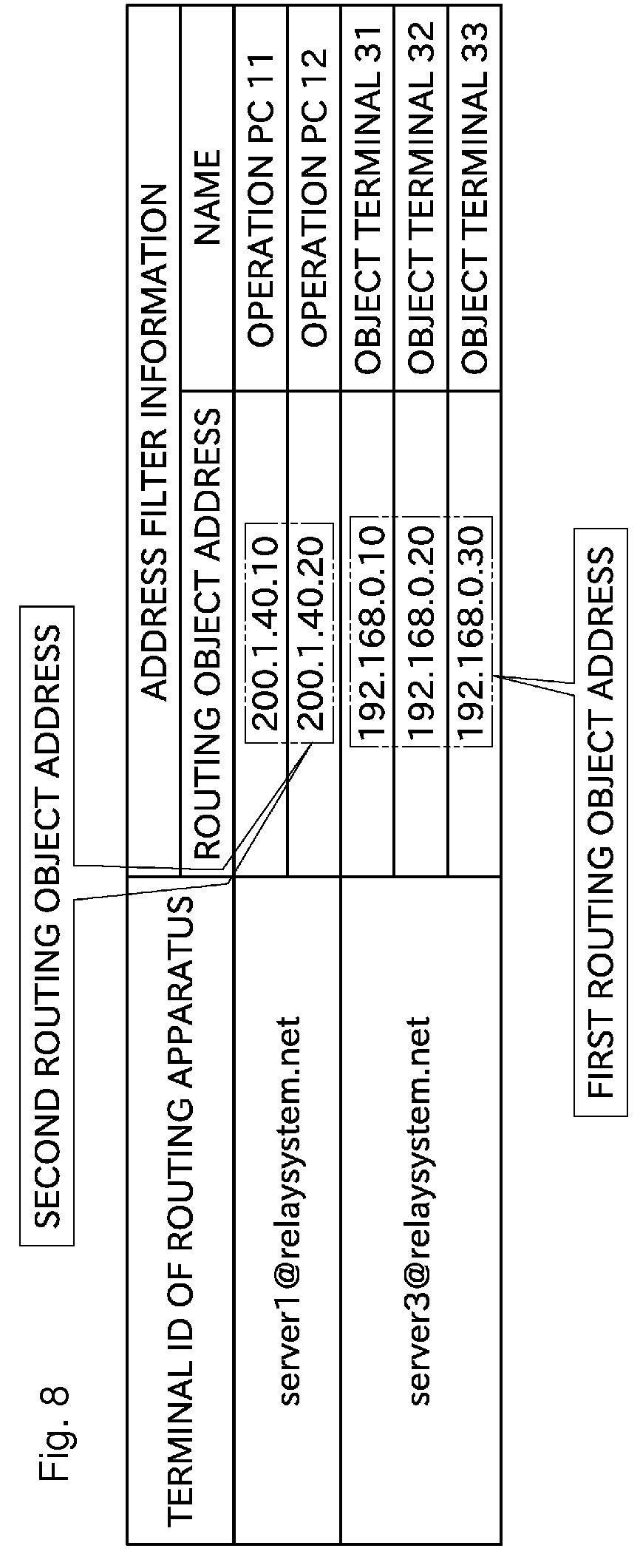
A relay server stores a routing apparatus belonging to a VPN group to which the relay server itself belongs, a second routing object address that is an address of the routing apparatus, and the like. The relay server stores a relationship of assignment of a virtual address to the second routing object address. The virtual address is an address that does not overlap with addresses of any other apparatuses. The relay server, upon receipt of a packet from a routing session, converts a source of the packet from an actual address into the virtual address and forwards the packet to a routing object device of the relay server itself. The relay server, upon receipt of a packet from the routing object device of the relay server itself, converts a destination of the packet from the virtual address into an actual address and forwards the packet to the routing session.

Description

BACKGROUND OF THE INVENTION[0001]1. Field of the Invention[0002]The present invention relates mainly to a relay server that enables communication to be performed between apparatuses connected to different LANs (Local Area Networks).[0003]2. Description of the Related Art[0004]Conventionally, a communication technology called a virtual private network (Virtual Private Network, VPN) has been known, which allows communication to be performed between LANs installed in physically distant places. Japanese Patent Application Laid-Open No. 2010-268312 shows an example in which a relay server, a communication terminal, and the like, are connected to each of a plurality of LANs installed in physically distant places. With use of the VPN, a communication terminal is able to transmit a packet to a communication terminal connected to another LAN. More specifically, a packet transmitted by a communication terminal is firstly sent to a relay server belonging to a LAN that the communication termina...

Claims


Application Information

Patent Timeline
Patent Type & Authority Patents(United States)
IPC IPC(8): H04L12/28H04L29/12H04L12/751H04L12/741H04L29/06H04L45/02H04L45/74
CPCH04L63/0272H04L45/02H04L45/74H04L61/2535H04L61/2007H04L61/5007
Inventor TANIMOTO, YOSHIFUMI
Owner MURATA MASCH LTD
Learn More