Sudas, uru and base station

a wireless communication network or system and base station technology, applied in the field of wireless communication networks or systems, can solve the problems of reducing the achievable data rate, ineffective outdoor-to-indoor communication using conventional mimo, and limited number of antennas that a ue can accommodate, so as to improve the quality of communication, save resources, and general availability of resources or bandwidth

Pending Publication Date: 2021-07-08
FRAUNHOFER GESELLSCHAFT ZUR FOERDERUNG DER ANGEWANDTEN FORSCHUNG EV
View PDF0 Cites 1 Cited by
  • Summary
  • Abstract
  • Description
  • Claims
  • Application Information

AI Technical Summary

Benefits of technology

[0029]According to a fourth aspect of the present invention, the inventors have found that a high quality of communication may be obtained by saving resources between the URU and the UE although a general availability of resources or bandwidth may be higher between the URU and the UE when compared to a bandwidth between the base station and the URU.
[0030]According to an embodiment of the fourth aspect, a URU is configured for operating as a relay for relaying a part of an input signal received from a base station to a user equipment. The URU comprises first interface for receiving the input signal from the base station using a plurality of resources. The URU comprises a signal generator configured for selecting a subset of resources from the plurality of resources and to provide an output signal using the selected subset of resources. The URU comprises a second interface for transmitting the output signal to the UE. This allows to avoid occupation of resources undedicated to the UE when forwarding the signal to the UE and therefore for saving resources and thus allows for a high quality of communication.

Problems solved by technology

However, outdoor-to-indoor communication using conventional MIMO is ineffective due to keyhole effect and large penetration losses which effectively reduce the achievable data rates [8].
Furthermore, due to the size constraints of user equipments (UEs), the number of antennas that a UE can accommodate is also limited.
Hence, UEs are unable to take advantage of spatial diversity to mitigate the losses.
However, joint processing entails high-speed interconnects between the relays to exchange the received MIMO signals, thereby increasing cost and reducing deployment flexibility.

Method used


Image

  • Sudas, uru and base station
  • Sudas, uru and base station
  • Sudas, uru and base station

Examples


Embodiment Construction

[0049]In the following, embodiments of the present invention are described in further detail with reference to the enclosed drawings in which elements having the same or a similar function are referenced by the same reference signs.

[0050]Although, in the following, reference is made to OFDM networks and / or LTE networks, embodiments described herein are not limited hereto. Without any limitation, a single-carrier transmission system may be implemented.

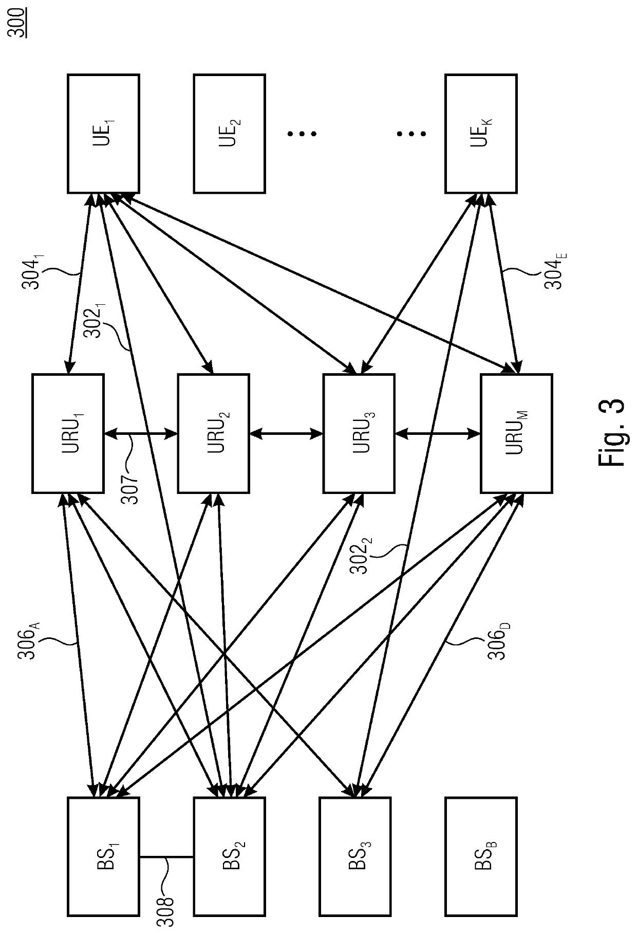
[0051]FIG. 3 shows a schematic block diagram of a SUDAS 300 (Shared User Equipment (UE)-side distributed antenna system) being an example network according to embodiments of the aspects described herein. Embodiments of the present invention are advantageous for networks comprising at least one base station (BS; eNB), at least one user equipment (UE) and at least one UE-side radio side unit (URU) relaying signals between the BS and the UE, embodiments are especially advantageous for networks comprising a plurality of UE, URU and / or BS, i...


PUM


Abstract

A SUDAS has at least one URU, wherein the at least one URU is configured for relaying a signal between at least one base station and at least one user equipment by communicating with the at least one user equipment in a first frequency range and with at least one base station in a second frequency range. The SUDAS has a controller configured for determining a first solution for a resource allocation in the first frequency range. The base station is configured for determining a second solution for a resource allocation in the first frequency range using the first solution.

Description

CROSS-REFERENCE TO RELATED APPLICATION[0001]This application is a continuation of copending International Application No. PCT / EP2018 / 075746, filed Sep. 24, 2018, which is incorporated herein by reference in its entirety.BACKGROUND OF THE INVENTION[0002]The present invention concerns the field of wireless communication networks or systems, more specifically concepts for relaying a signal in wireless communication networks or systems. The present invention refers to a Shared User Equipment (UE)-side distributed antenna system (SUDAS) comprising UE-side radio units (URU) for relaying signals between a base station and a UE. The present invention further relates to a concept for handling and controlling a SUDAS being a shared relaying system useful for 5G and next generation automotive and mobile broadband services.[0003]High data rate outdoor-to-indoor communication and in-door coverage are crucial requirements for next generation communication systems [7]. For high data rate applicati...

Claims


Application Information

Patent Timeline
Patent Type & Authority Applications(United States)
IPC IPC(8): H04W88/04H04B7/155H04W52/34H04W52/46H04W76/14H04L5/00
CPCH04W88/04H04B7/15542H04L5/0098H04W52/46H04W76/14H04W52/346H04B7/0456
Inventor SCHOBER, ROBERTBREILING, MARCOKRISHNAMOORTHY, ARAVINDH
Owner FRAUNHOFER GESELLSCHAFT ZUR FOERDERUNG DER ANGEWANDTEN FORSCHUNG EV
Why Eureka
Try Eureka