Image processing apparatus and image processing method

a technology of image processing and image processing, applied in the direction of image enhancement, geometric image transformation, instruments, etc., can solve the problems of line dropout, distortion of read image, and greater sharpening effect, and achieve high-quality interpolation

Active Publication Date: 2016-05-24
CANON KK
View PDF6 Cites 2 Cited by
  • Summary
  • Abstract
  • Description
  • Claims
  • Application Information

AI Technical Summary

Benefits of technology

[0008]The present invention provides an image processing apparatus and an image processing method capable of handling variations in spatial frequency occurring when a target is converted into image information, and obtaining a high-quality interpolation result.
[0010]According to the present invention, it is possible to handle variations in spatial frequency occurring when a target is converted into image information and obtain a high-quality interpolation result. For example, when carrying out distortion correction, magnification processing, or the like on an image obtained from a non-planar document, or when carrying out distortion aberration correction, chromatic aberration correction, or the like caused by an optical system when converting a target into image information, a high-quality interpolation result that has no unevenness within the overall image can be obtained while carrying out highly-accurate interpolation processing.

Problems solved by technology

However, distortion occurs in the read image when the distance from the image capturing unit is not constant, and thus it is necessary to correct the distortion.
However, this method is problematic in that jaggies, line dropouts, and so on will arise.
Conversely, a narrower reference region relative to the pre-processing image or a higher frequency of the sampling function results in a greater sharpening effect being produced on the pre-processing image and more jaggies in edge areas.
Meanwhile, even if the tilt of the document relative to the document platform is constant, the captured image may distort in, for example, a barrel shape due to optical distortion present in the camera's optical system itself.
As a result, unevenness appears in the effect on the post-distortion correction process image.

Method used


Image

  • Image processing apparatus and image processing method
  • Image processing apparatus and image processing method
  • Image processing apparatus and image processing method

Examples


first embodiment

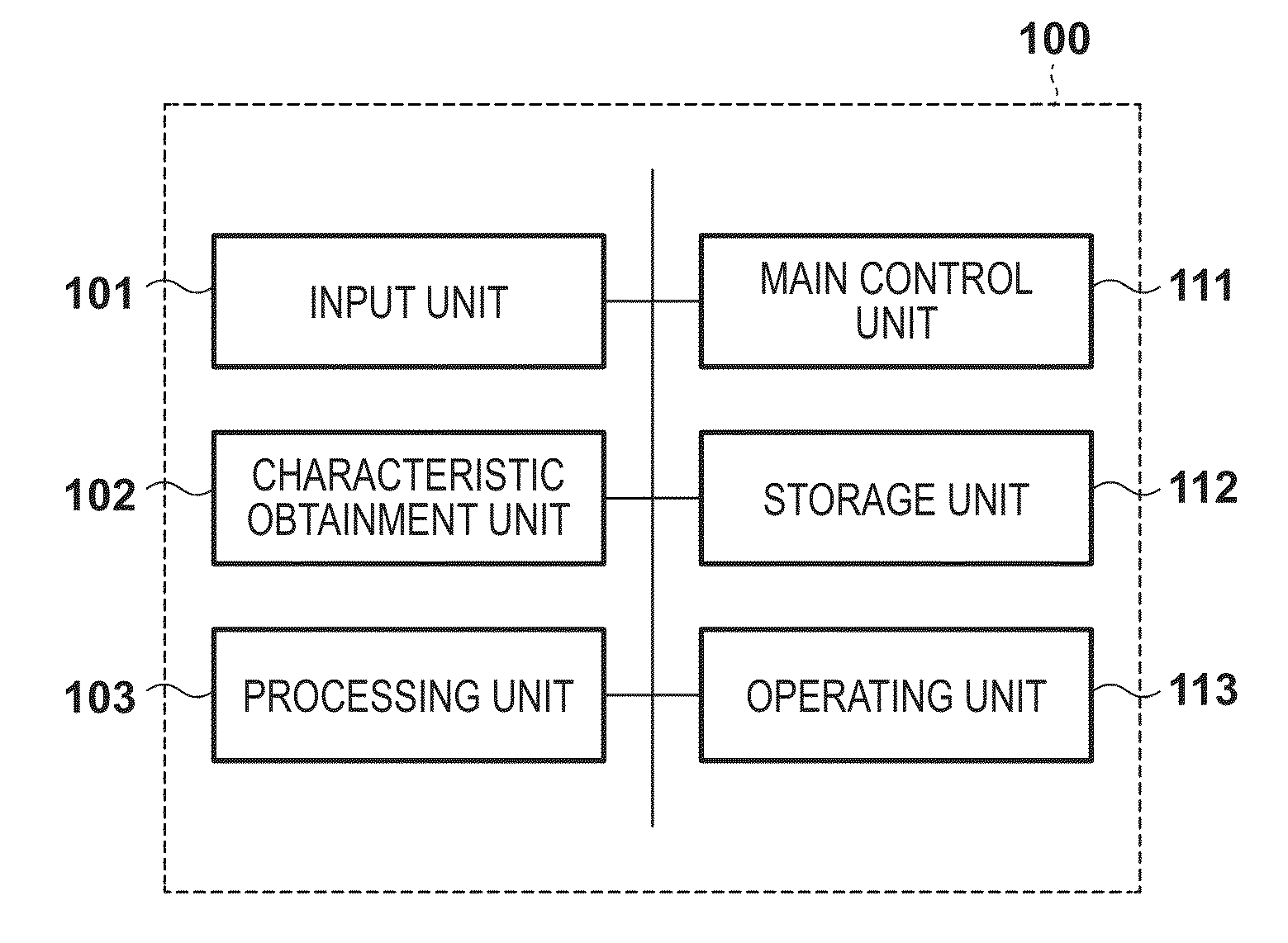
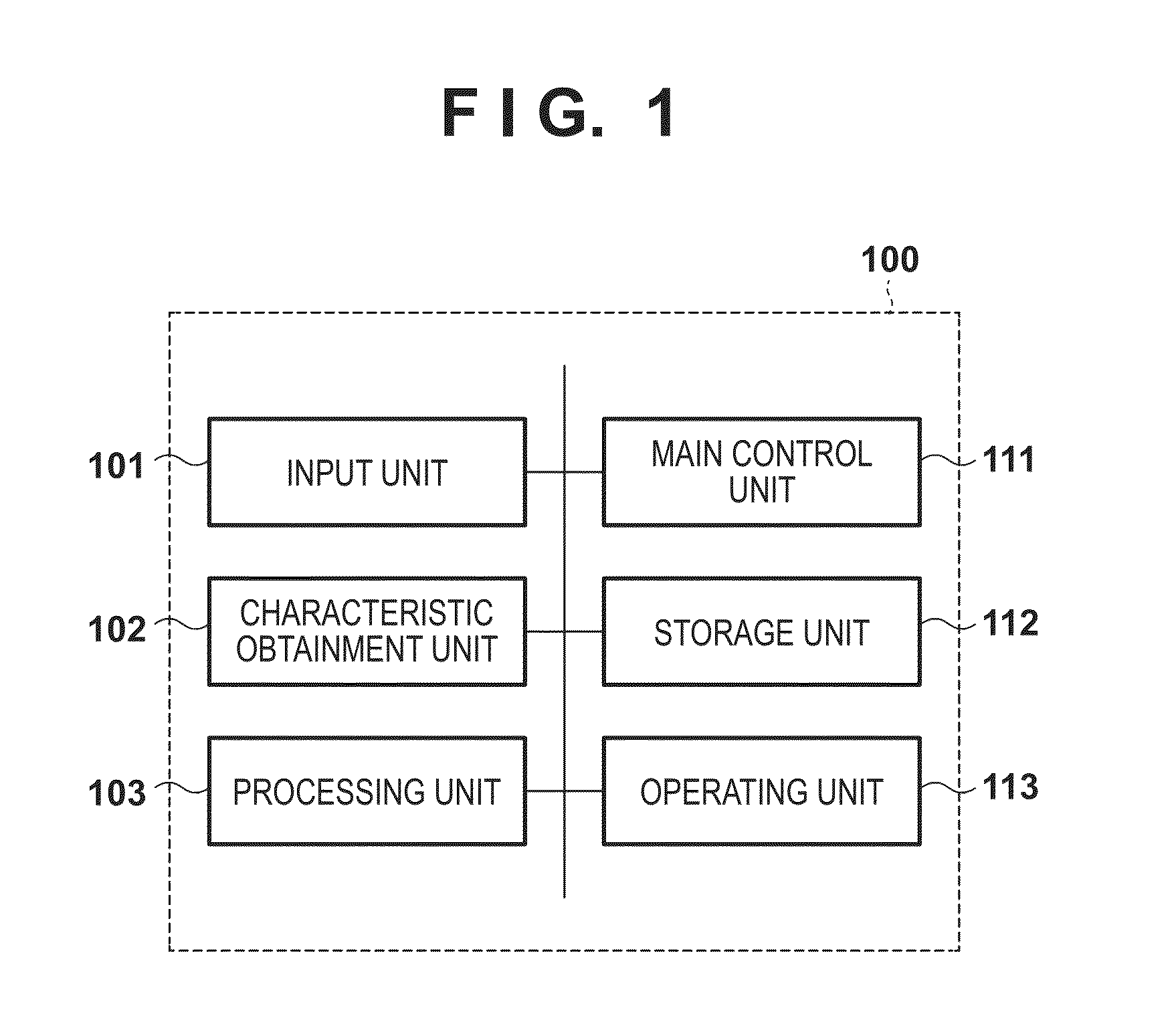
[0028]The first embodiment describes, as an embodiment of an image processing apparatus according to the present invention, a document reader that captures an image using a camera and carries out a distortion correction process on the captured image. FIG. 1 is a block diagram illustrating a configuration according to the present embodiment. A document reader 100 according to the present embodiment includes a main control unit 111 that controls an image reading apparatus as a whole, a storage unit 112 that stores captured image data and accompanying information, and an operating unit 113 that receives commands from an operator. The document reader 100 further includes an input unit 101 that captures an image of a document and inputs resulting electronic image data, a characteristic obtainment unit 102 that obtains distortion characteristics of the document, and a processing unit 103 that carries out the distortion correction process on the captured image. The obtained electronic imag...

second embodiment

[0048]The first embodiment describes changing the reference region in accordance with tilt in the document in the convolution operation that is carried out using the sampling function. The second embodiment describes a configuration of a document reader provided with a distortion correction process that switches the frequency characteristics of the sampling function rather than varying the region.

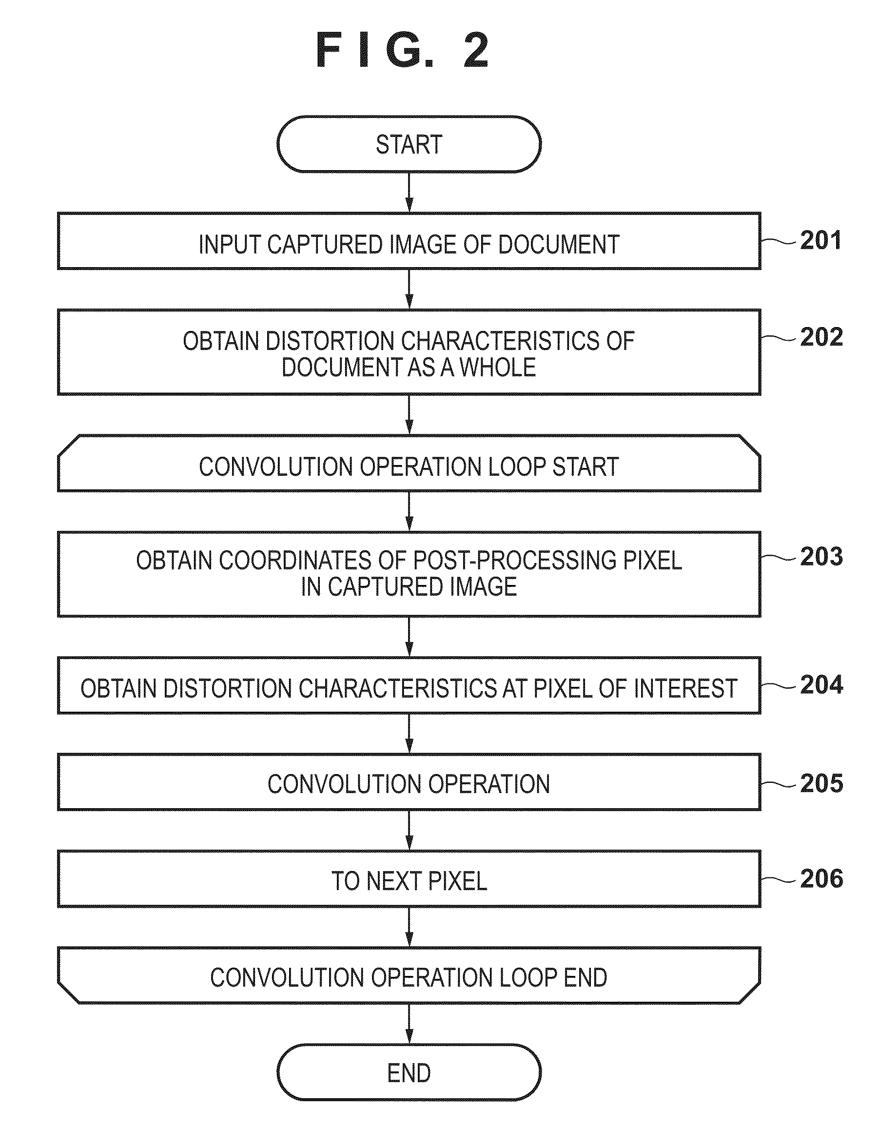
[0049]A block diagram illustrating the configuration of the present embodiment is the same as in the first embodiment, and thus follows FIG. 1. Furthermore, the flow of operations is the same as in the first embodiment, and thus follows FIG. 2. The second embodiment differs from the first embodiment in that in step 205, the frequency characteristics are switched in accordance with the tilt of the document when the convolution operation is carried out. In other words, a calculation using Formula 14 is carried out as a calculation in place of Formula 9 from the first embodiment.

[0050]tgtval=∫...

third embodiment

[0058]In the convolution operation carried out using the sampling function, the first embodiment describes changing the reference region thereof in accordance with the tilt of the document, and the second embodiment describes changing the frequency characteristics of the sampling function in accordance with the tilt of the document. The third embodiment describes a document reader provided with a distortion correction process that carries out both of these processes.

[0059]A block diagram illustrating the configuration of the present embodiment and an operational flowchart are the same as in the first embodiment and the second embodiment, and thus follow FIG. 1 and FIG. 2.

[0060]The third embodiment differs from the first embodiment and the second embodiment in that in step 205, both the reference region and the frequency characteristics are switched in accordance with the tilt of the document when the convolution operation is carried out. In other words, a calculation using Formula 1...


PUM


Abstract

An image processing apparatus processes image data configured of pixels disposed in grid form. The apparatus includes an obtaining unit that obtains distortion characteristics indicating characteristics of distortion in a target contained in original image data obtained by capturing an image of the target, and a correction unit that, using a sampling function, interpolates a pixel of interest in the original image data, based on pixels of the original image data present in a reference region in the periphery of the location of the pixel of interest. The correction unit changes the range of the reference region, the frequency characteristics of the sampling function, or both in accordance with the distortion characteristics.

Description

BACKGROUND OF THE INVENTION[0001]1. Field of the Invention[0002]The present invention relates to image processing apparatuses and image processing methods that carry out image processing on an image.[0003]2. Description of the Related Art[0004]Image reading apparatuses that obtain image data by capturing an image of a document on a document platform from directly above or at an angle from above using an image capturing unit such as a camera, a scanner, or the like have been known for some time, as represented by document cameras. However, distortion occurs in the read image when the distance from the image capturing unit is not constant, and thus it is necessary to correct the distortion. To obtain post-distortion correction process pixel values for given pixels in such a distortion correction process, it is necessary to obtain relative post-distortion correction process coordinates of the pixel in the pre-correction process image, as well as carrying out an interpolation process th...

Claims


Application Information

Patent Timeline
Patent Type & Authority Patents(United States)
IPC IPC(8): H04N1/407G06T5/00G06T3/00H04N1/00H04N1/024
CPCH04N1/02481G06T3/0093G06T5/006H04N1/00005H04N1/00013H04N1/00045H04N1/00087H04N1/02409
Inventor SANO, SHINJI
Owner CANON KK
Why Eureka
Try Eureka