
Lead pin rectifying apparatus and lead pin rectifying method

a lead pin and rectifying apparatus technology, applied in the direction of manufacturing tools, semiconductor lasers, shaping tools, etc., can solve the problems of reducing the positioning accuracy of semiconductor lasers, increasing assembly time, and increasing the operation efficiency of semiconductor lasers, so as to achieve efficient rectifying of lead pins

Inactive Publication Date: 2016-05-31
RICOH KK
View PDF14 Cites 0 Cited by
  • Summary
  • Abstract
  • Description
  • Claims
  • Application Information

AI Technical Summary

Benefits of technology

The apparatus efficiently rectifies lead pins without causing damage or contamination, reduces manufacturing costs, and maintains high positioning accuracy, enabling effective assembly with reduced operational time and improved optical characteristics.

Problems solved by technology

However, as a pitch (a distance) between neighboring lead holes is narrow and a diameter of a circle formed by multiple lead holes is small, there may occur a failure such as a solder bridge and an increase in assembly time due to a decrease in operational efficiency when the lead pins are soldered to the print circuit board.
Therefore, fine particles, fragments, etc., are produced, and, with the produced fine particles and fragments, positioning accuracy of the semiconductor laser decreases and problems of deterioration of optical characteristics and pollution of other optical components may Occur.
Moreover, a lead pin may get caught in the wall portion of the straight hole, so that bending of the lead pin may occur, unnecessary work and time may arise due to altering, disposing, etc., possibly leading to an increased cost.
Therefore, in Patent document 2, there is a problem of increasing manufacturing cost.
Moreover, in the method of rectifying the lead pin in Patent document 2, excessive stress may be exerted at a root of the lead pin when rectifying the shape of the lead pin, so that the lead pin may be damaged.
As described above, there is a problem that the lead pin is not efficiently rectified with related art methods of rectifying the lead pin.

Method used


Image

  • Lead pin rectifying apparatus and lead pin rectifying method
  • Lead pin rectifying apparatus and lead pin rectifying method
  • Lead pin rectifying apparatus and lead pin rectifying method

Examples


Embodiment Construction

[0024]Below embodiments to which a lead pin rectifying apparatus and a lead pin rectifying method of the present invention are applied are described.

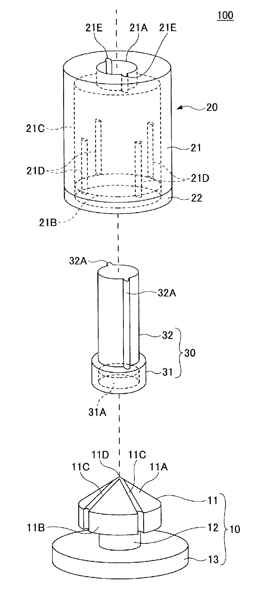
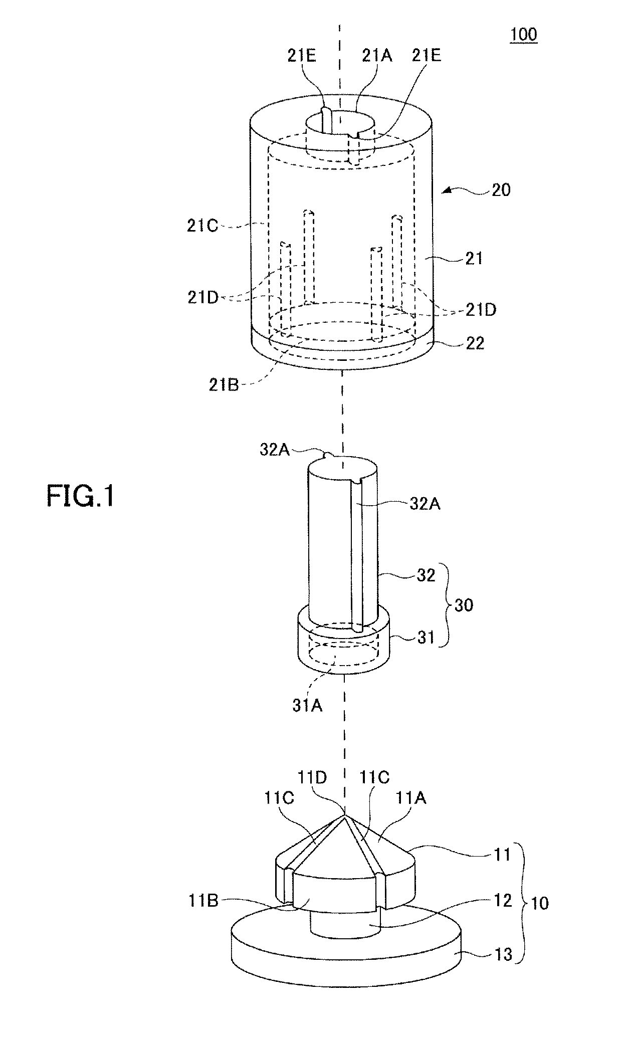
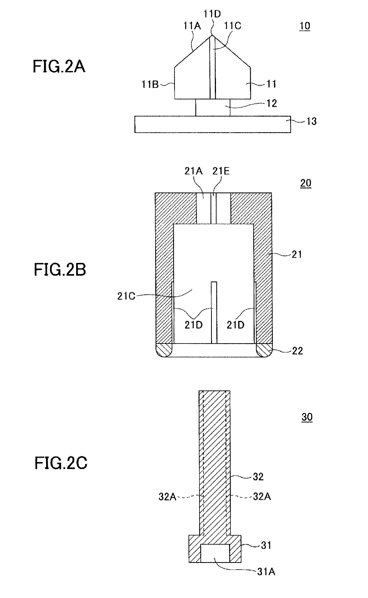
[0025]FIG. 1 is an exploded perspective view showing a lead pin rectifying apparatus according to an embodiment. FIGS. 2A, 2B, and 2C are diagrams showing a cross-sectional structure of the lead pin rectifying apparatus according to the embodiment.

[0026]A lead pin rectifying apparatus 100 of the embodiment includes a lower side rectifying portion 10, an upper side rectifying portion 20, and a pressing member 30. Cross sections shown in FIGS. 2A to 2C are respectively a cross section which passes through a central axis of the lower side rectifying portion 10, the upper side rectifying portion 20, and the pressing member 30.

[0027]The lower side rectifying portion 10, which is an example of a first member, includes a head portion 11, an intermediary portion 12, and a base portion 13. The head portion 11 includes a tapered upper face 11A, a...


PUM

PropertyMeasurementUnit
inner diameteraaaaaaaaaa

Abstract

A lead pin rectifying apparatus is provided, including a first member which includes a tapered upper face and a cylindrically-shaped side face; a cylindrically-shaped second member which has an inner diameter corresponding to an outer diameter of the first member, wherein the second member covers over the first member therewith while an electronic component having the lead pin is housed inside the second member; and a pressing member which presses the electronic component to the first member from the top side of the second member while housing the electronic component having the lead pin inside the second member to abut the lead pin against an upper face of the first member, wherein the second member is pressed to the first member after pressing the electronic component to the first member with the pressing member to rectify the shape of the lead pin of the electronic component.

Description

TECHNICAL FIELD[0001]The present invention relates to lead pin rectifying apparatuses and lead pin rectifying methods.BACKGROUND ART[0002]In conjunction with a trend towards multi-beam laser diodes in semiconductor laser apparatuses, the semiconductor laser apparatuses now include multiple lead pins. Moreover, there is a trend towards high density of mounting onto a printed circuit board. Therefore, there arises a need to provide, within a narrow region of the printed circuit board, multiple lead holes for inserting the lead pins.[0003]The lead pins are inserted into the lead holes provided at the printed circuit board to be fastened by soldering. The lead holes are arranged on generally the same circumference in a plane view.[0004]However, as a pitch (a distance) between neighboring lead holes is narrow and a diameter of a circle formed by multiple lead holes is small, there may occur a failure such as a solder bridge and an increase in assembly time due to a decrease in operationa...

Claims


Application Information

Patent Timeline
Patent Type & Authority Patents(United States)
IPC IPC(8): B21F1/00H05K13/02H05K13/00H01S5/022
CPCB21F1/004H05K13/0092H05K13/023H01S5/02212
Inventor ANDOH, FUMIKATA
Owner RICOH KK
Learn More