

Lead pin rectifying apparatus and lead pin rectifying method
- Summary
- Abstract
- Description
- Claims
- Application Information
AI Technical Summary
Benefits of technology
Problems solved by technology
Method used
Image

Examples
Embodiment Construction
[0024]Below embodiments to which a lead pin rectifying apparatus and a lead pin rectifying method of the present invention are applied are described.
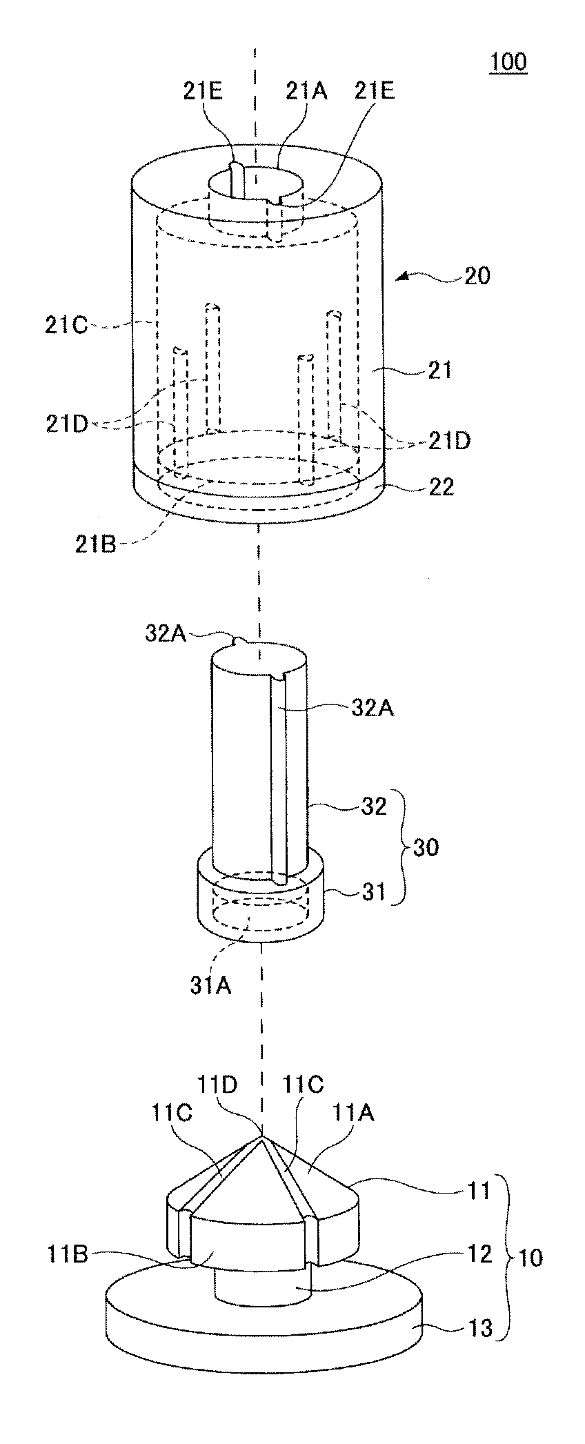
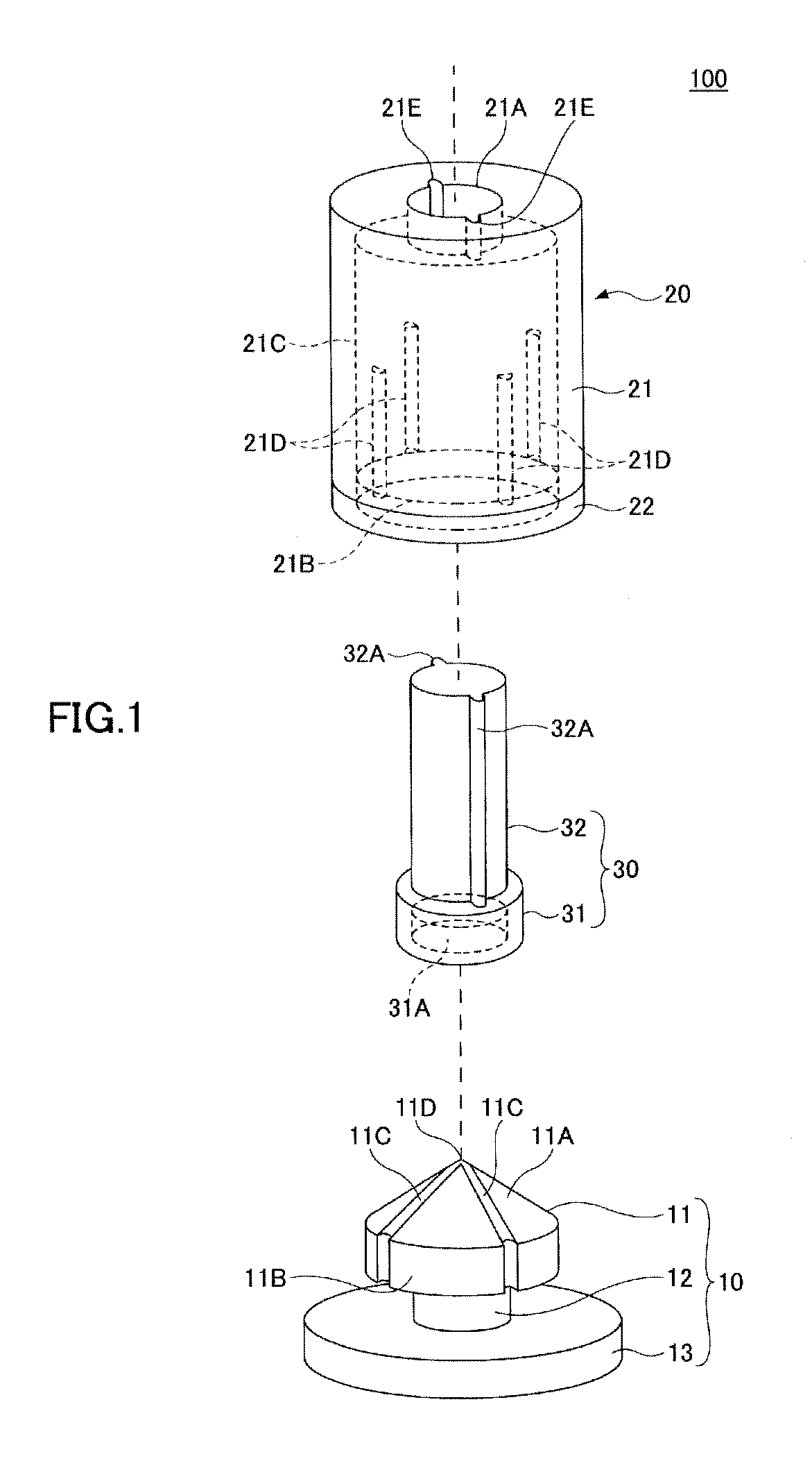
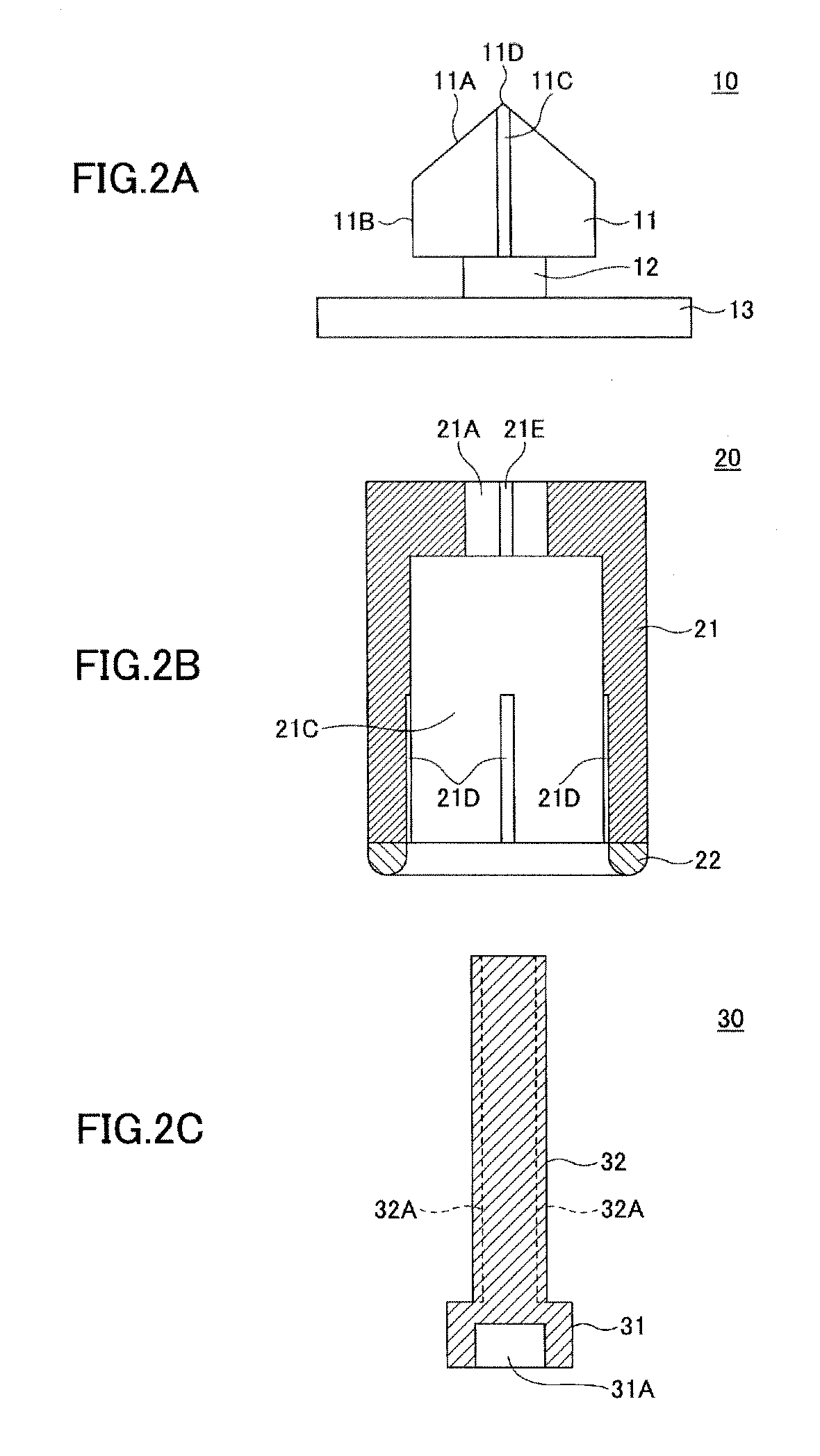
[0025]FIG. 1 is an exploded perspective view showing a lead pin rectifying apparatus according to an embodiment. FIGS. 2A, 2B, and 2C are diagrams showing a cross-sectional structure of the lead pin rectifying apparatus according to the embodiment.
[0026]A lead pin rectifying apparatus 100 of the embodiment includes a lower side rectifying portion 10, an upper side rectifying portion 20, and a pressing member 30. Cross sections shown in FIGS. 2A to 2C are respectively a cross section which passes through a central axis of the lower side rectifying portion 10, the upper side rectifying portion 20, and the pressing member 30.
[0027]The lower side rectifying portion 10, which is an example of a first member, includes a head portion 11, an intermediary portion 12, and a base portion 13. The head portion 11 includes a tapered upper face 11A, a...
PUM
| Property | Measurement | Unit |
|---|---|---|
| Diameter | aaaaa | aaaaa |
| Elasticity | aaaaa | aaaaa |
| aaaaa | aaaaa |
Abstract
Description
Claims
Application Information