Powering microcontrollers

a microcontroller and power supply technology, applied in the field of powering microcontrollers, can solve the problems of difficult to provide suitable dc power to the microcontroller from a power source of the product, e.g. from a battery or derived from a mains supply, and achieve the effect of efficiently powering itself, preventing unwanted discharge of capacitance via said associated high-side switch, and efficient rectifying the ac waveform

Active Publication Date: 2022-04-05
KONINKLJIJKE PHILIPS NV
View PDF18 Cites 0 Cited by
  • Summary
  • Abstract
  • Description
  • Claims
  • Application Information

AI Technical Summary

Benefits of technology

[0009]This arrangement allows a microcontroller to receive an AC (alternating current) waveform and to efficiently rectify the AC waveform to provide a source of DC (direct current) power for powering the microcontroller. Since the associated high-side switch of the first output port is in the turned-off state when the voltage of the AC waveform at the first output port is lower than the voltage at the high-side DC voltage rail, unwanted discharge of the capacitance via said associated high-side switch is prevented. This means that the microcontroller can efficiently power itself from the AC waveform. This allows a microcontroller to be implemented without requiring an external source of DC power or external rectifier. Such a microcontroller could be implemented with a local source of AC power, such as may be produced by a wireless power receiver or an energy harvesting module as will be discussed in more detail later. The microcontroller can also output control signals for controlling at least one aspect of operation of a host device, i.e. a device in which the microcontroller in embedded, via at least one other output port.

Problems solved by technology

In some instances however, depending on the location of the microcontroller within the product, providing suitable DC power to the microcontroller from a power source of the product, e.g. from a battery or derived from a mains-supply, may not be straightforward.

Method used


Image

  • Powering microcontrollers
  • Powering microcontrollers
  • Powering microcontrollers

Examples


Embodiment Construction

[0029]Various types of electronic shaver products are known. Such products typically have one or more movable cutting elements that, in use, are driven to provide a cutting action. For instance in some shaver products one or more rotatable cutting elements may be provided.

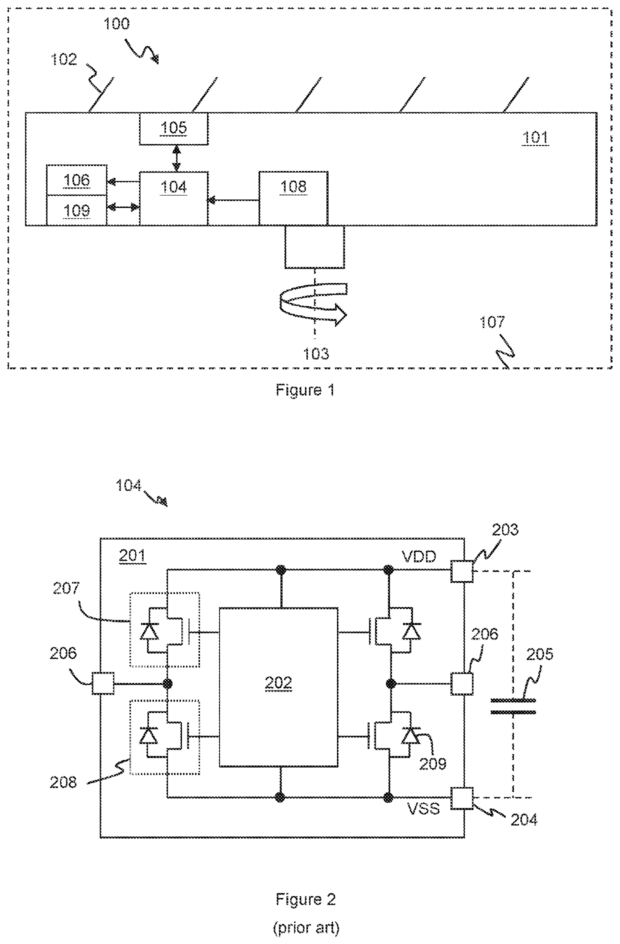
[0030]An improved or personalised user experience may be realised by sensing shaving conditions during shaving and adapting at least one aspect of the shaver operation to the sensed conditions. In some instances it may be beneficial to respond to the conditions at the cutting element, and thus it has been proposed to provide sensing and / or control at the location of the cutting element. At least some aspects of sensing and control may be provided by a microcontroller located at the location of the cutting element, for instance a microcontroller may be located on, or as part of, the structure of a rotating cutting element.

[0031]FIG. 1 illustrates this principle. FIG. 1 illustrates generically a cutting element 100. ...


PUM


Abstract

This application relates to methods and apparatus for powering microcontrollers (104), in particular for powering microcontrollers of a personal care product, such as a shaver product (107). The microcontroller is arranged such that a first output port (206-1) of a plurality of output ports of the microcontroller receives, in use, an AC waveform. Each output port has an associated high-side switch (207) electrically connected between the output port and a high-side DC voltage rail and an associated low-side switch (208) electrically connected between the output port and a low-side DC voltage rail. A processing module (202) of the microcontroller is configured to monitor a phase of the AC waveform and to control switching of the associated high-side and low-side switches of the first output port based on the phase of the AC waveform so as to provide a rectified voltage between the high-side DC voltage rail and the low-side voltage rail for powering the processing module. The processing module (202) also controls switching of the associated switches of at least a further output port to output a control signal for controlling at least one aspect of operation of a host device. The processing module is further configured to maintain the associated high-side switch of the first output port in a turned-off state when a monitored voltage of the AC waveform at the first output port is between zero and a monitored voltage at the high-side DC voltage rail, and to maintain the associated high-side switch of the first output port in a turned-on state when the monitored voltage of the AC waveform at the first output port is greater than the monitored voltage at the high-side DC voltage rail.

Description

CROSS REFERENCE TO RELATED APPLICATIONS[0001]This application is the U.S. National Phase application under 35 U.S.C. § 371 of International Application No. PCT / EP2018 / 085613 filed Dec. 18, 2018, published as WO 2019 / 121755 on Jun. 27, 2019, which claims the benefit of European Patent Application Number 17208321.4 filed Dec. 19, 2017. These applications are hereby incorporated by reference herein.FIELD OF THE INVENTION[0002]This disclosure relates to powering of microcontrollers, in particular for powering microcontrollers of a personal care product, such as a shaver product.BACKGROUND OF THE INVENTION[0003]Microcontrollers are relatively small control circuits, typically having at least one processor and some memory and configurable to provide some sensing and / or control functionality via a variety of general purpose input-output (GPIO) ports.[0004]Microcontrollers may be embedded into a variety of electronic products to provide sensing and / or control functionality, for instance to ...

Claims


Application Information

Patent Timeline
Patent Type & Authority Patents(United States)
IPC IPC(8): H02M7/219B26B19/38H02M7/217H02M1/088H02M1/08H02M1/00G01R19/165G01R19/175
CPCH02M7/219B26B19/3873G01R19/16538G01R19/175H02M1/0003H02M1/0048H02M1/082H02M1/083H02M1/088H02M7/217H02M1/08H02M1/081H02M5/4585
Inventor VELTMAN, EDDY GERRIT
Owner KONINKLJIJKE PHILIPS NV
Why Eureka
Try Eureka