Reel

a technology of flanges and flanges, applied in the field of flanges, can solve the problems of affecting the axial direction position of the other flange, changing the axial direction position of the one flange, etc., and achieve the effect of improving the axial direction position of the flanges with respect to the hub

Active Publication Date: 2016-05-31
FUJIFILM CORP
View PDF12 Cites 2 Cited by
  • Summary
  • Abstract
  • Description
  • Claims
  • Application Information

AI Technical Summary

Benefits of technology

[0007]Therefore, it is an object of the present invention to obtain a reel in which the precision of the axial direction positions of the flanges with respect to the hub can be improved in a structure that can suppress changes in the axial direction positions of the flanges caused by deformation of the hub caused by tightening of the recording tape.
[0009]According to the first aspect pertaining to the present invention, the first inner peripheral portion and the second inner peripheral portion contact the first reference surface and the second reference surface, respectively, formed on the connecting portion of the hub, whereby the first flange and the second flange are positioned in the axial direction with respect to the hub. Additionally, in this state, the first insertion portions and the second insertion portions are inserted into the through holes formed at the connecting portion and are joined together. Consequently, the precision of the axial direction positions of the flanges with respect to the hub can be improved compared to a configuration where positioning is performed at axial direction end surfaces of the hub or joint sections. Furthermore, because of this positioning, both axial direction end surfaces of the hub (the cylinder portion) do not touch the first flange surface and the second flange surface. Thus, changes in the axial direction positions of the first flange and the second flange caused by deformation of the hub caused by tightening of the recording tape can be suppressed.
[0011]According to the second aspect pertaining to the present invention, the positions of the first insertion portions and the second insertion portions joined together inside the through holes in the connecting portion and the first reference surface and the second reference surface are near one another, so compared to a configuration in which the positions of the joint sections and the first reference surface and the second reference surface are far from one another, the precision of the axial direction positions of the flanges with respect to the hub can be further improved.
[0015]According to the fourth aspect pertaining to the present invention, the first flange and the second flange can be molded using one mold, so their manufacturing cost can be reduced.
[0017]According to the fifth aspect pertaining to the present invention, the axial center portion and the connecting portion are interconnected via the deformation absorbing portion that is formed in an annular shape and has a substantially U-shaped cross section, so deformation of the hub caused by tightening of the recording tape can be absorbed, and changes in the axial direction positions of the first flange and the second flange caused by that deformation can be suppressed, by the deformation absorbing portion.

Problems solved by technology

However, when the hub and the one flange are directly joined together, there is the concern that the axial direction position of that one flange will end up changing due to deformation of the hub caused by tightening of the recording tape.
Furthermore, when the hub with which the one flange has been integrally molded is removed from a mold, the axial direction end surface of the hub is ejected by an ejector pin, but when that end surface serves as a reference surface for defining the axial direction position of the other flange, there is the concern that this will affect the precision of the axial direction position of the other flange.

Method used


Image

  • Reel
  • Reel
  • Reel

Examples


Embodiment Construction

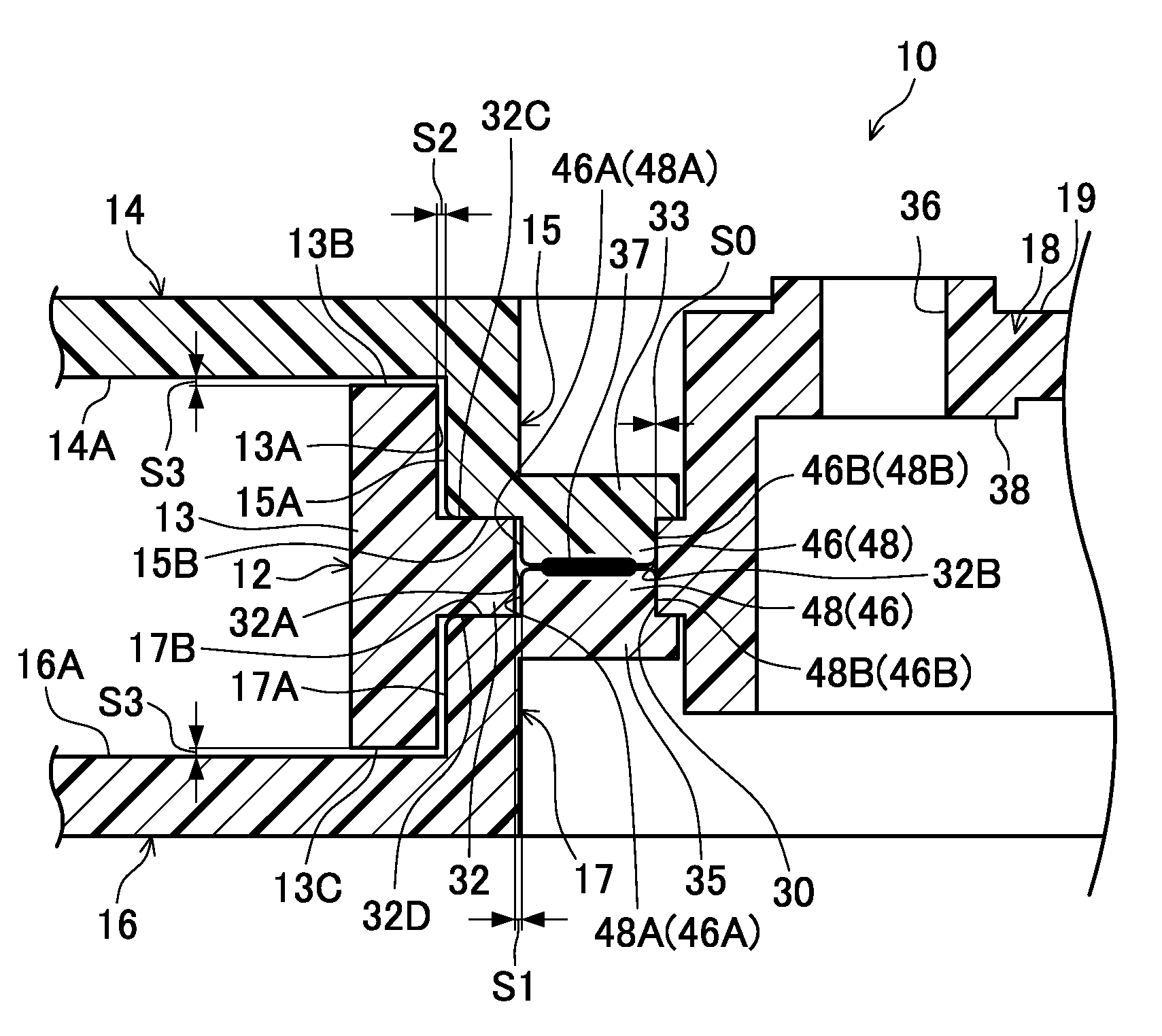
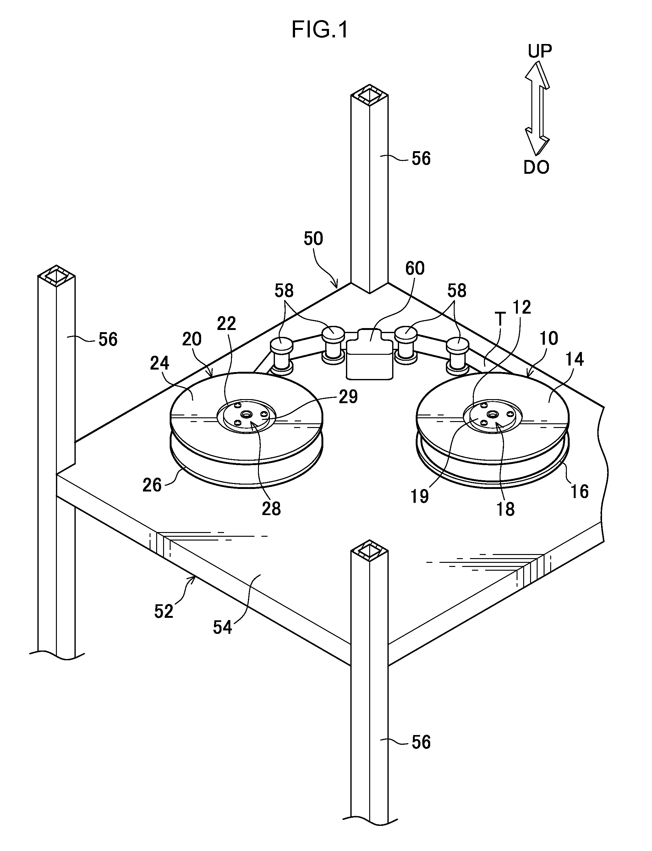
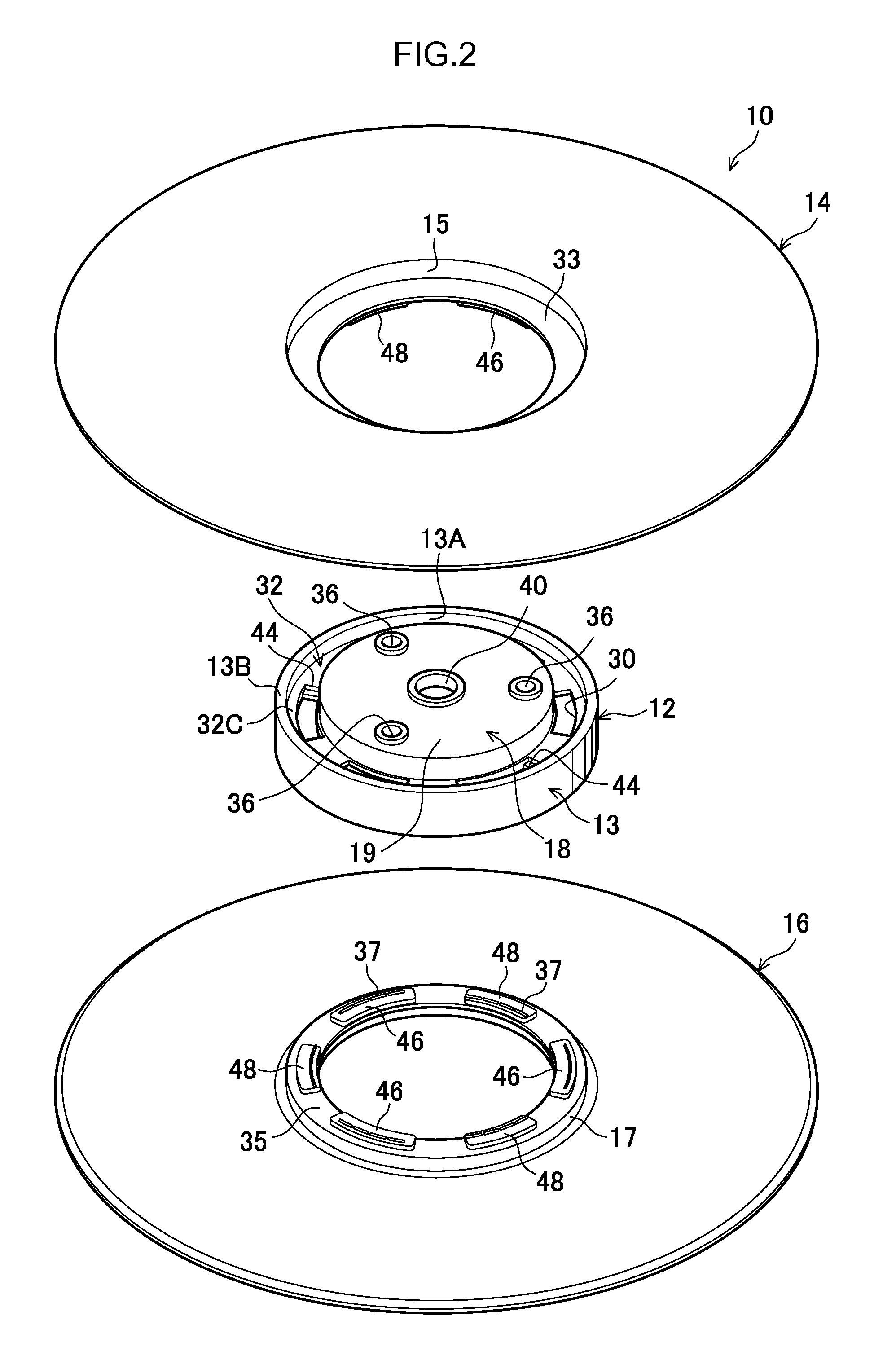
[0030]Embodiments pertaining to the present invention will be described in detail below on the basis of the drawings. For convenience of description, arrow UP in FIG. 1 denotes an up direction, arrow DO denotes a down direction, and a rotational axis direction of reels 10 and 20 pertaining to the embodiments coincides with the up and down direction (height direction). Furthermore, initially an overview of a drive device 50 in which the reels 10 and 20 are detachably disposed will be described, and then the configurations of the reels 10 and 20 will be described in detail. First, a first embodiment will be described.

[0031]

[0032]The reels 10 and 20 pertaining to the present embodiment are molded in the same shape using a synthetic resin material such as polycarbonate (PC), for example. Additionally, as shown in FIG. 1, the reels 10 and 20 are disposed as a pair inside a casing 52 (in FIG. 1, only a bottom plate 54 and three struts 56 are shown) of the drive device 50.

[0033]The reel 10...


PUM

PropertyMeasurementUnit
shapeaaaaaaaaaa
heightaaaaaaaaaa
widthaaaaaaaaaa

Abstract

A reel includes: a hub in which plural through holes are formed at a connecting portion that interconnects a cylinder portion and an axial center portion; a first flange that is disposed on one end portion of the hub and equipped with a first inner peripheral portion, which contacts a first reference surface formed on the connecting portion and ensures that a first flange surface does not touch the cylinder portion, and first insertion portions, which are inserted into the through holes; and a second flange that is disposed on the other end portion of the hub and equipped with a second inner peripheral portion, which contacts a second reference surface formed on the connecting portion and ensures that a second flange surface does not touch the cylinder portion, and second insertion portions, which are inserted into the through holes and are joined together with the first insertion portions.

Description

CROSS-REFERENCE TO RELATED APPLICATION[0001]This application is a continuation application of International Application No. PCT / JP2012 / 080390, filed Nov. 22, 2012, the disclosure of which is incorporated herein by reference in its entirety. Further, this application claims priority from Japanese Patent Application No. 2012-082921, filed Mar. 30, 2012, the disclosure of which is incorporated herein by reference in its entirety.BACKGROUND[0002]1. Technical Field[0003]The present invention relates to a reel around which recording tape such as magnetic tape is wound.[0004]2. Related Art[0005]As a resin reel housed in a recording tape cartridge, there is a reel in which a hub and one flange are integrally molded, with a section where another flange is welded to the hub and a section where the axial direction position of the other flange is positioned with respect to the hub being disposed in different positions so that the precision with which they are welded together is improved (e.g., ...

Claims


Application Information

Patent Timeline
Patent Type & Authority Patents(United States)
IPC IPC(8): B65H75/18G11B23/04G11B23/113G11B23/037B65H75/22
CPCB65H75/22G11B23/037G11B23/044G11B23/113B65H75/2245B65H75/2272
Inventor MORI, YASUHIRO
Owner FUJIFILM CORP
Why Eureka
Try Eureka