
Switchgear enclosure housing assembly including an extendable conductor assembly

a technology of extendable conductors and enclosure housings, which is applied in the direction of switchgear earthing arrangements, bus-bar/wire layouts, and metal casing arrangements, etc., can solve the problems of increasing the difficulty of physically locating large conductive bars that extend the full length of the housing assembly, reducing the overall size of the electrical switching apparatus and the associated housing assembly, and high cost of large ground bars

Inactive Publication Date: 2016-05-31
EATON INTELLIGENT POWER LTD
View PDF6 Cites 7 Cited by
  • Summary
  • Abstract
  • Description
  • Claims
  • Application Information

AI Technical Summary

Benefits of technology

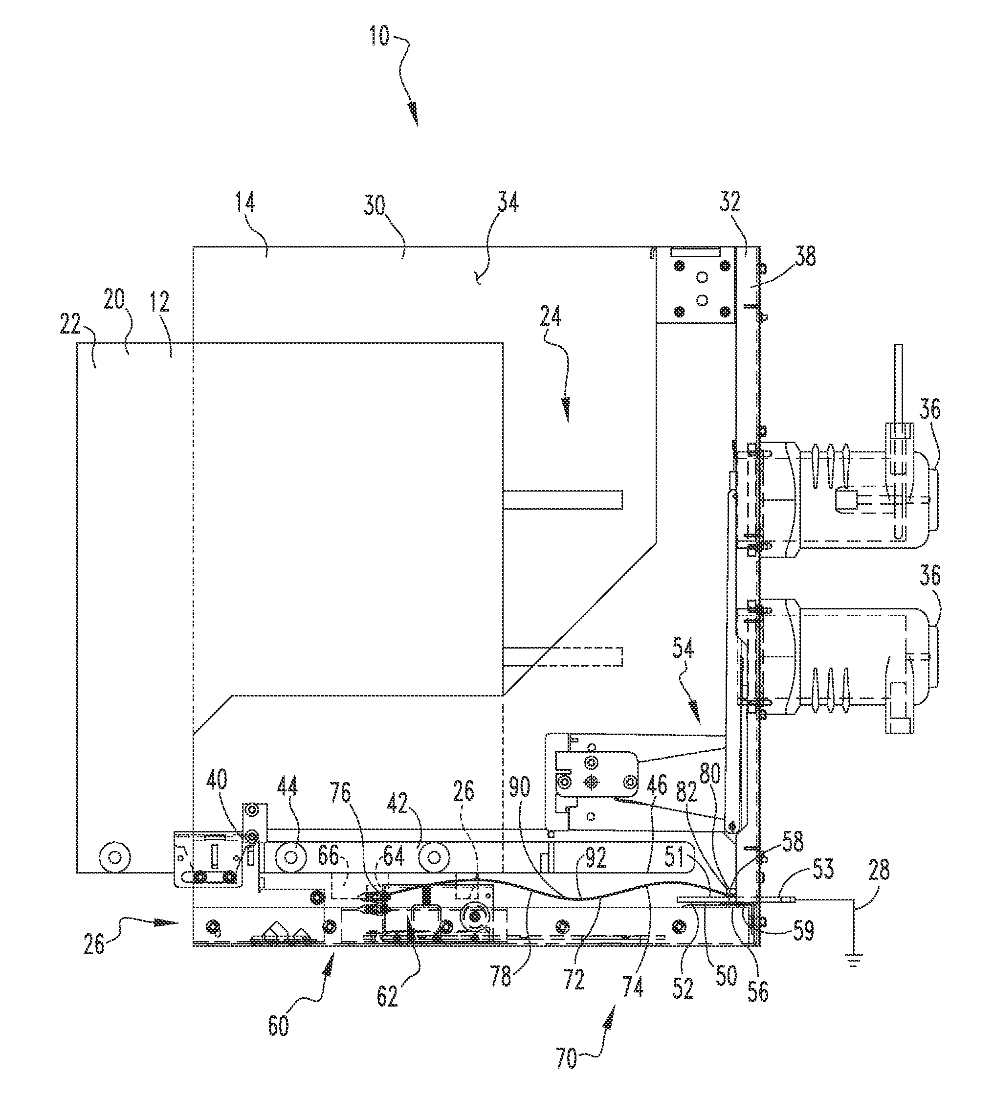
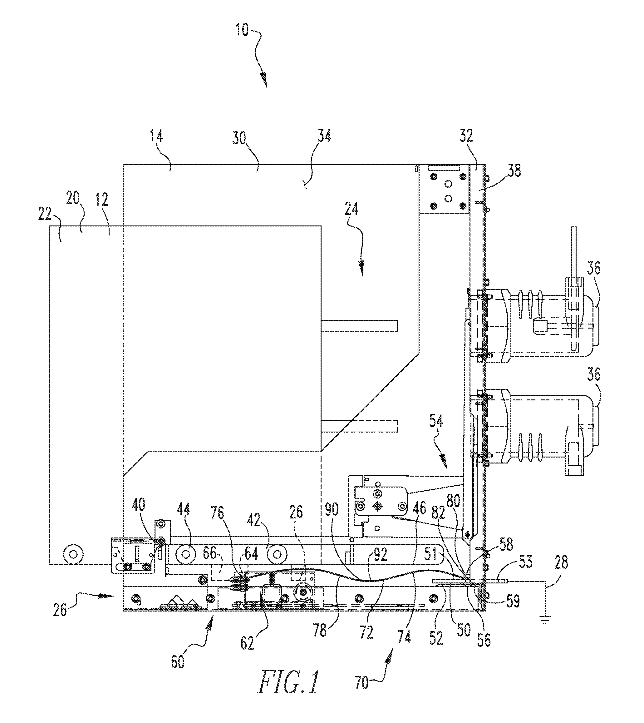
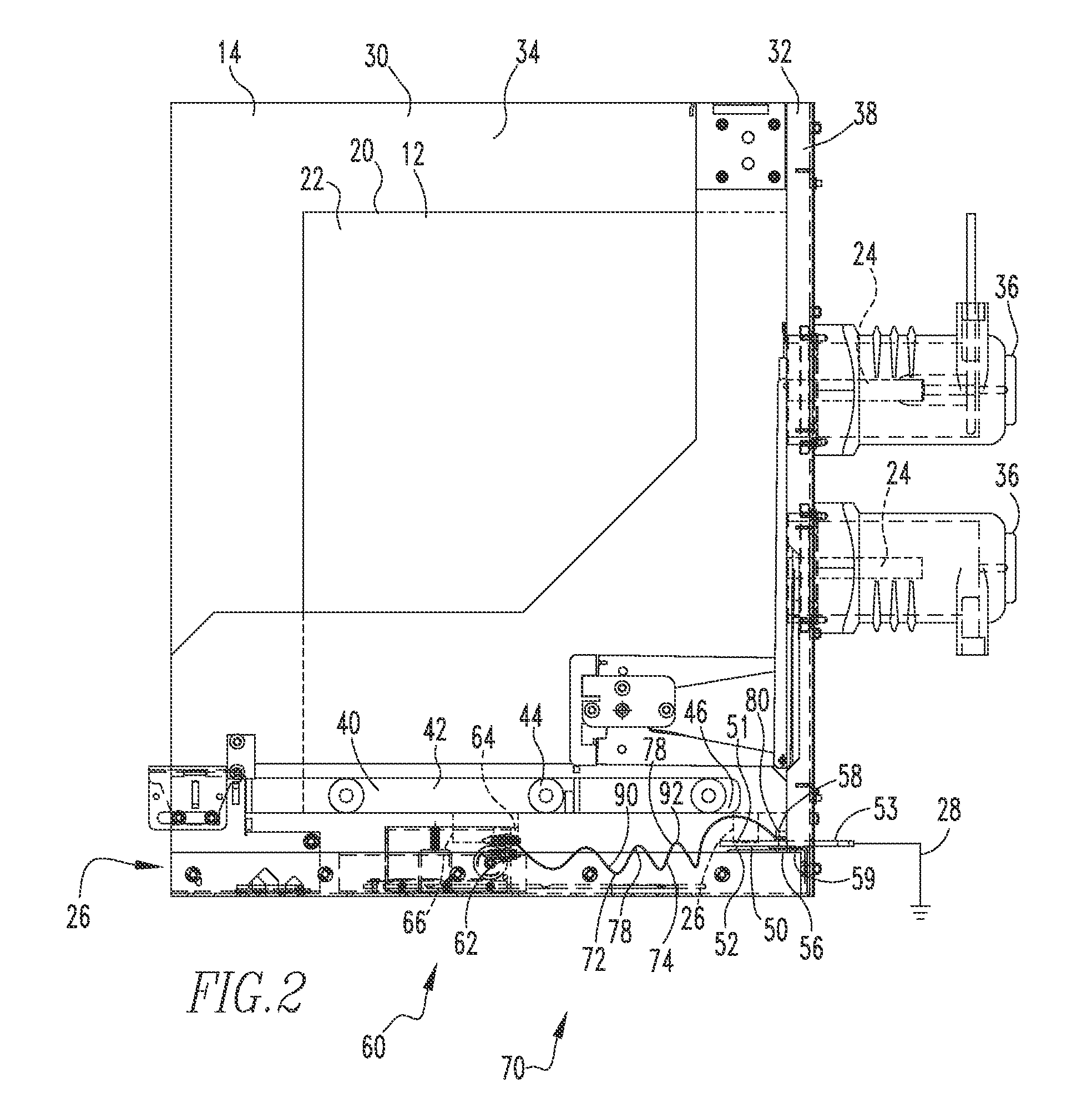
The disclosed patent is for a housing assembly for an electrical switching apparatus that has a sidewall assembly, a movable carriage assembly, a ground bus bar assembly, and a movable terminal assembly with an extendable conductor assembly. The movable terminal assembly is grounded and moves with the movable carriage assembly. The extendable conductor assembly has a first and second configuration and is used to connect the movable terminal assembly to the ground bus bar assembly. The technical effect of this invention is that it provides a secure and reliable grounding path for the movable terminal assembly and allows for easy movement between different positions within the housing assembly.

Problems solved by technology

Because advancing technology continually reduces the overall size of an electrical switching apparatus and the associated housing assembly, physically locating large conductive bars that extend the full length of the housing assembly is becoming increasingly difficult.
Additionally, market demand for copper makes large ground bars expensive.

Method used


Image

  • Switchgear enclosure housing assembly including an extendable conductor assembly
  • Switchgear enclosure housing assembly including an extendable conductor assembly
  • Switchgear enclosure housing assembly including an extendable conductor assembly

Examples


Embodiment Construction

[0015]Directional phrases used herein, such as, for example, clockwise, counterclockwise, left, right, top, bottom, upwards, downwards and derivatives thereof, relate to the orientation of the elements shown in the drawings and are not limiting upon the claims unless expressly recited therein.

[0016]As used herein, the singular form of “a,”“an,” and “the” include plural references unless the context clearly dictates otherwise.

[0017]As used herein, the statement that two or more parts or components are “coupled” shall mean that the parts are joined or operate together either directly or indirectly, i.e., through one or more intermediate parts or components, so long as a link occurs. An element resting on another element with no other connection, however, is not linked and therefore is not “coupled.” For example, a pen resting on a desk is not “coupled” thereto. A pen chained to a desk is “coupled” thereto. Further, when two elements are coupled, all portions of those elements are coup...


PUM


Abstract

An enclosure housing assembly for an electrical switching apparatus is provided. The enclosure housing assembly includes a sidewall assembly, a movable carriage assembly, a ground bus bar assembly and a movable terminal assembly with an extendable conductor assembly. The sidewall assembly includes a number of sidewalls defining an enclosed space. The movable carriage assembly is movable between a withdrawn, first position. Wherein the movable carriage assembly is disposed partially outside the enclosure sidewall assembly enclosed space, and an inserted, second position, wherein the movable carriage assembly is disposed substantially inside the enclosure sidewall assembly enclosed space. The ground bus bar assembly is coupled to the first sidewall. The movable terminal assembly is coupled to the movable carriage assembly whereby the movable terminal assembly moves with the movable carriage assembly. The extendable conductor assembly is coupled to, and in electrical communication with, the ground bus bar assembly.

Description

BACKGROUND OF THE INVENTION[0001]1. Field of the Invention[0002]The disclosed concept relates to a switchgear and, more particularly, to a switchgear wherein an enclosure housing assembly includes an extendable conductor assembly and a ground bus bar assembly that does not extend over the path of travel of a movable carriage assembly.[0003]2. Background Information[0004]Electrical switching apparatus, such as but not limited to circuit breakers, are often disposed in an enclosure or housing assembly. The electrical switching apparatus is disposed on, or is incorporated with, a movable carriage assembly. When the electrical switching apparatus need repair or other maintenance, the electrical switching apparatus is drawn, at least partially, from the enclosure. The removal of the electrical switching apparatus from the housing assembly may, or may not, decouple the electrical switching apparatus from the power source (hereinafter “line”) and / or the load. For the safety of the operator...

Claims


Application Information

Patent Timeline
Patent Type & Authority Patents(United States)
IPC IPC(8): H02B1/20H02B11/28H02B13/02
CPCH02B11/28H02B13/02
Inventor RICCIUTI, ANTHONY THOMASBRANDT, DOUGLAS MICHAEL
Owner EATON INTELLIGENT POWER LTD
Learn More